|
|
 |
| The Original |
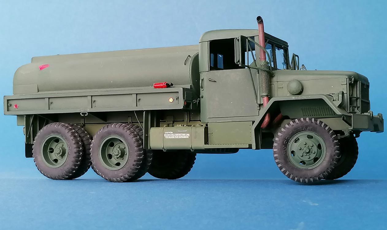
The successors of the 2 ½ ton GMC CCKW "Jimmy" of WWII and Korean War fame, the trucks of the M35 series, have been produced in just as many variants as their forerunners and become just as famous, not least in Viet Nam.
| The kit |
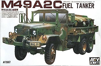
AFV Club has made the basic M35 with some different loads in the back, like the subject of this build, the 1200 gallon fuel tanker M49A2C. The kit is over 20 years old, with most of the parts for chassis and cab coming from the even older M35 molds. – I used parts from the Eduard PE sets 35 109 and 35 439.
| The build |
CHASSIS
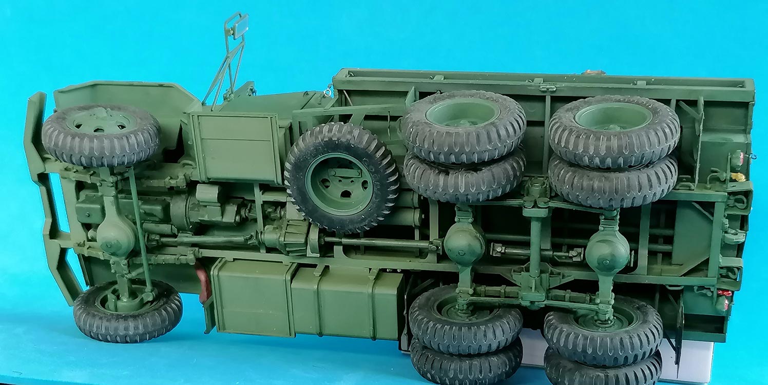
 All tiedown eyes on the frame were replaced with rectangular ones from copper wire, with "welds" from wire insulation slices, and two more were added on either side, right behind the front bumper and above the first rear axle. I didn't install the winch, but cut off the Power Takeoff at the end of the drive shaft and cemented that to the gear box A46/47. On part A60, the compressed air reservoirs, the carrying bars were extended to the opposite frame rail. About in the middle of both frame rails, there are two thin vertical bars that represent spiral springs; I removed the moldings and replaced them with thin wire wrapped around stretched sprue.
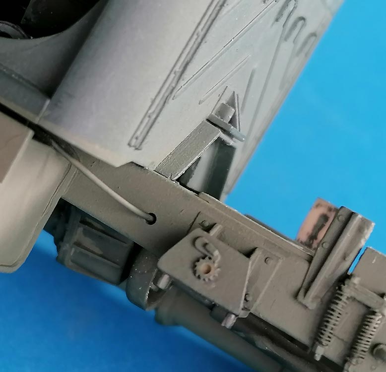
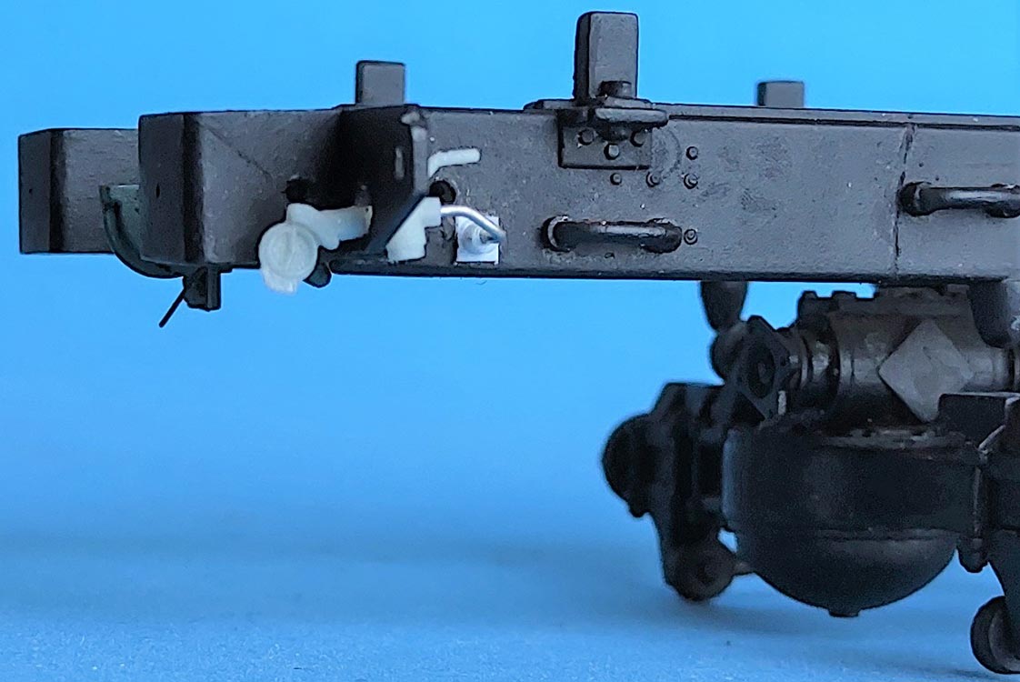
 In front of the spare wheel carrier, a cable of unknown purpose was added, coming out of a hole in the frame and going towards the bottom of the cab. – On the chassis fuel tank, the holding braces and their counterparts on the frame rail needed some workover before they cooperated. The molded-on tube towards the frame was removed and replaced with one of 0.5mm rod, and two thin electrical leads were added from stretched vinyl sprue.
It is advisable to dry fit the close seat of the load bed on the frame rails now, while any necessary corrections can still be made without lots of details in the way.
All wheels had 0.3mm brass wire valve stems added. Steering linkage A23,24,30 had holes drilled through for stretched sprue to join them movably to each other and A23's mounting pin was extended so it would pass through the chassis frame and could be secured with a sheet styrene circle on the inside. Rear axle springs A54 were not glued to the frame, the drive shafts were only dry fitted and trailing arms A13,14 were held in place only by friction and a little paint. This preserved some flexibility of the drivetrain, allowing all wheels to touch the ground before cement was applied where necessary on the finished model. The spare wheel had a "bar with studs" added to its underside.
 I made the pintle operating, and all towing eyes A57 and their respective mounting points were drilled through so they could be installed movably with stretched sprue. The rear bumperettes A17/18 had holes drilled into their outward flanges to allow the insertion of pins that hold A57 here for trailer securing chains. Speaking of trailers: AFV hasn't provided gladhands for their air brakes. I bought PSM #35083, but found them sub-ideal: The valve handles are pointing to the couplings, while the latter have a hemispheric side opposite the coupling ridges, and missing are the protectors that are installed when there's no recipient attached. I sanded down the hemispheres and then drilled through the whole contraption; the two parts were then sawed apart so that after reversing the half with the handle, they could be joined again on a suitable wire.
 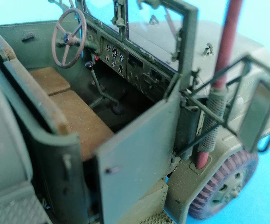 This wire was stuck into holes drilled into the frame rails and pokes through holes of 2mm dia. that were drilled into the tail light braces to bring the handle on the front side of the brace and the coupling behind it. As for the protectors, I couldn't think of an easy way to make them, so they're MIA on my model.
I didn't want to paint the glass representations of tail lights and front marker lights, so I cut off the "glass" and sanded replacements from clear sprue. Aluminum foil off Christmas or Easter chocolate candy provided the material for red and amber backgrounds with Future/Pledge as the adhesive. – The exhaust pipe had its passage through the fender pimped with a "seal" from thin sheet.
HOOD / CAB
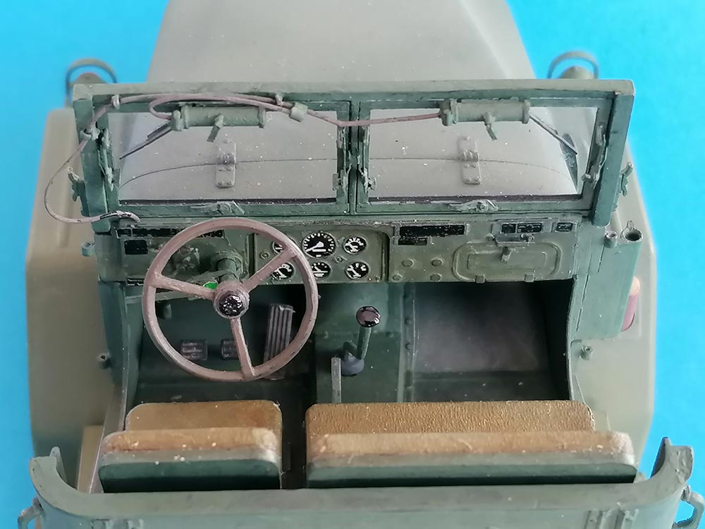
 Whenever a model kit offers separate doors, I want them to be operating, so I constructed hinges: 2 x 2mm plastic sheet squares had one side chamfered so that two pieces of 1mm dia. stretched plastic tubing could be glued into the notch formed by the chamfers – one to the top half, the other to the opposite lower half. Stretched sprue with a molten end makes the hinge pins, and the squares were glued into recesses cut into doors and frames. All seat "fabric" was represented with a single layer of paper handkerchief that was affixed with dabbed-on thin liquid cement. To further set my model apart, I gave the driver's seat a workover to change it into the later model as in AFV Club's M54.
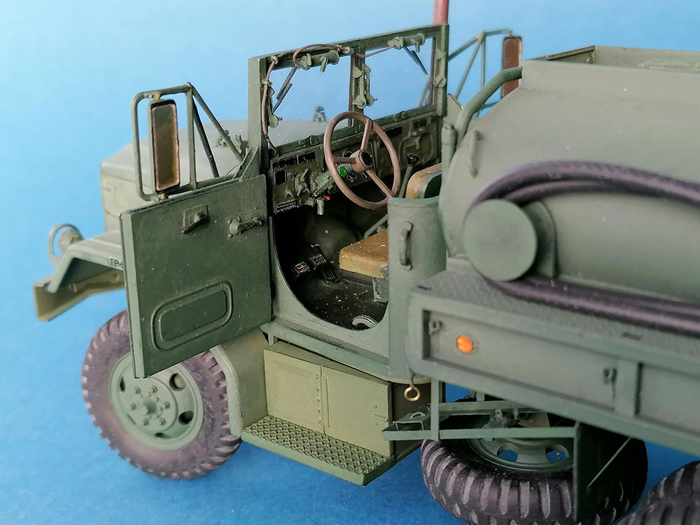 Behind it, I added a hardly detectable PTO lever for the fuel tank pump (and winch, where installed). The M54 kit also let me see what the missing indicator lever on the steering column had to look like. Eduard provided the dashboard, to which I added the red Engine Start Button and the Air Cleaner Indicator below a new steering column. The kit decals for the dash unfortunately were printed in black only, so they are hardly visible against the dark background; the instrument bezels came from Eduard.
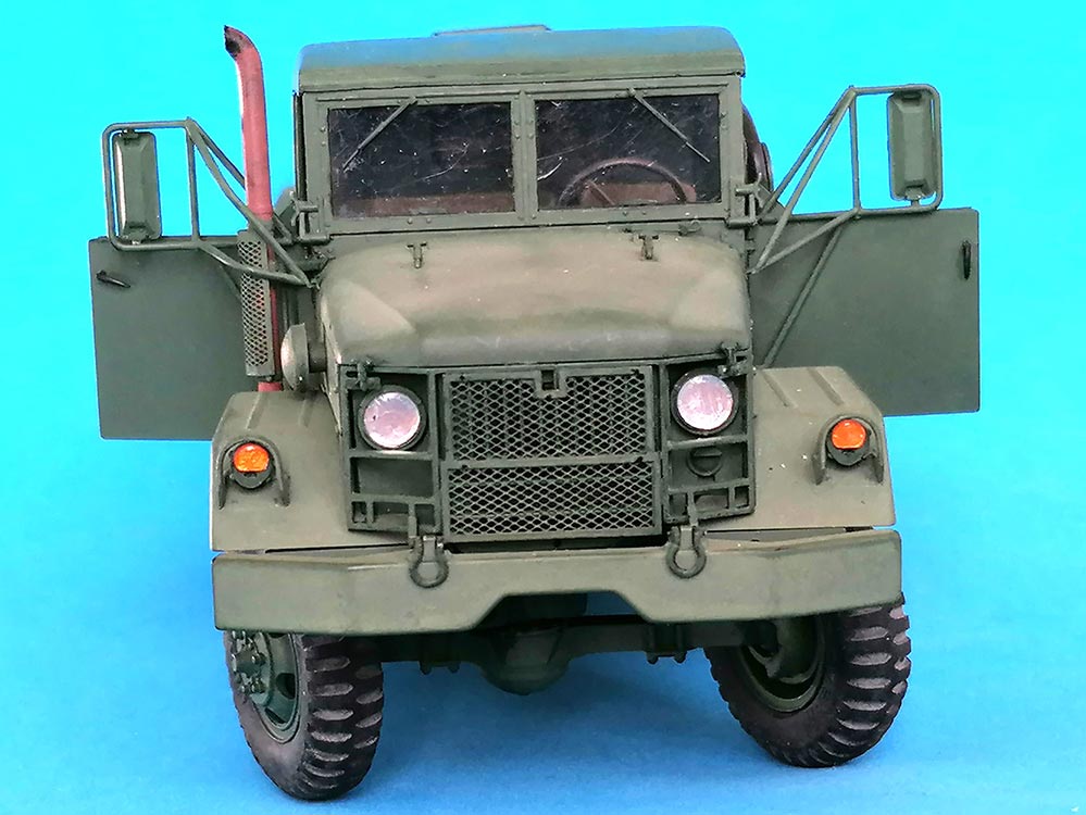
 It took me a while to find the second pair of hold down latches B49 in the instructions – seems like AFV Club added them as an afterthought and didn't really know where to mount them and how. I took 0.25 x 1mm wide styrene strips and stuck tiny ovals of PlaPaper to them after drilling in small locating holes and making "rivets" next to them by pressing in a blunt needle from the back side. The upper end of the latches is held by a "fork" under their handle that was made by drilling a hole into styrene strip and then cutting that in half. – While in the area, I added a frame from thin styrene strips around the PE engine grill, with white glue dot "bolts".
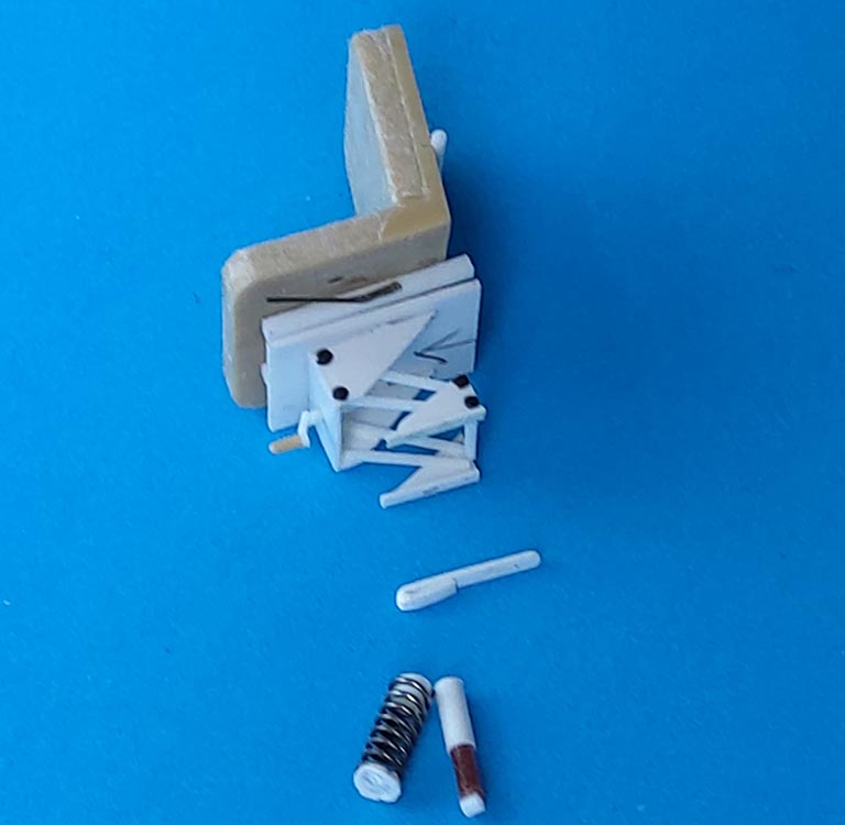
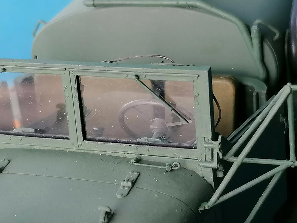
The kit's windscreen is rather simplistic, like with the push-out mechanism for the panes molded to the clear parts. After removing the wiper imitations, the first measure was to install stretched black sprue as outer window seals for acetate 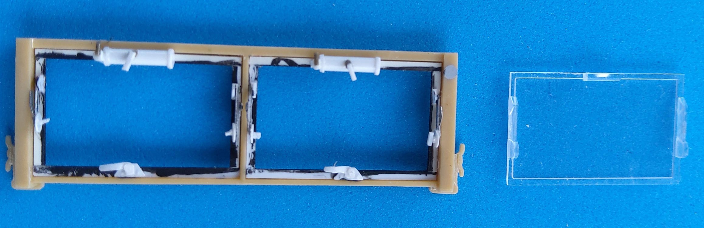 (bubble pack) panes whose inside frames were made from 0.25 x 1mm Evergreen strips. Wiper motors were made of 1.5 x 6mm plastic rod with ends of 0.5 x 2mm and switches from scratch plus stretched vinyl sprue "air hoses". The push-out mechanisms are made from 2mm dia. thin styrene sheet disks with 0.25 x 0.5 x 2mm handles and printer's aluminum braces of 1 x 5mm and 1 x 3mm, respectively, plus little styrene triangles. The arresters at the bottom were cut and bent from thin styrene sheet. Wiper arms are from strip styrene slivers and the blades from styrene sheet. – Right in front of the driver's pane, the "open hood support hook" from fine brass wire was mounted on the cowling.
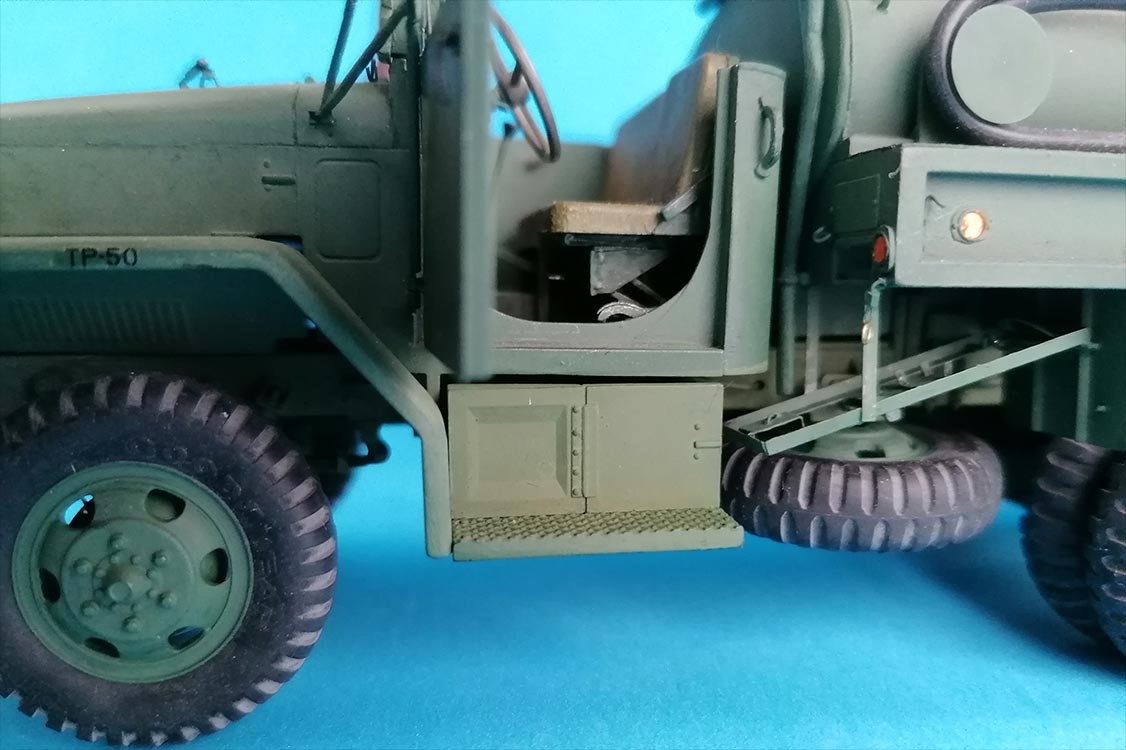
The doors received PE triangles on their tops and grooves for "rolled down windows" of 0.5 x 0.5mm strips. The window cranks were carefully separated from their background and had their knobs extended, while the opening handles inside and out were replaced by ones from styrene rod sanded into shape. Behind the passenger door opening, below the handle there is a rectangular depression into which I glued a piece of sprue as slave cable receptacle.
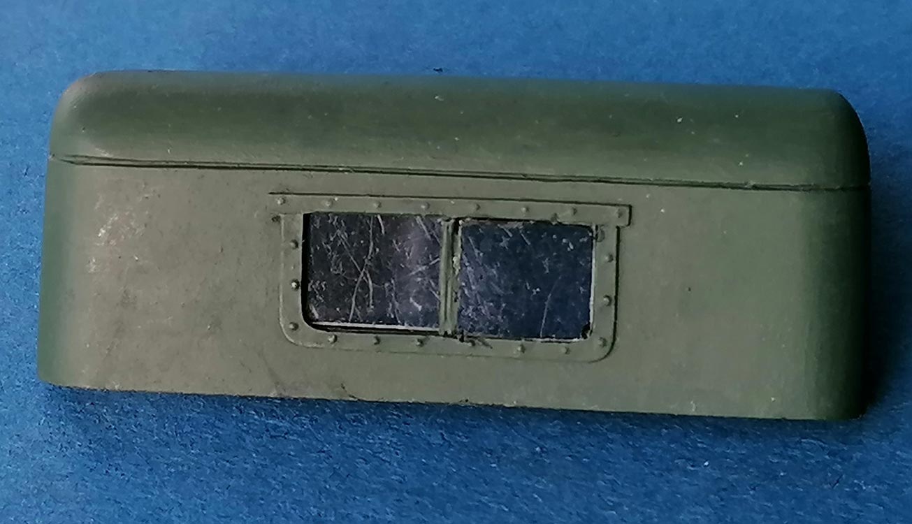 Regarding the mirrors, I went for the more elaborate version. The main braces were mounted to the doors' hinge pins, taking great care to keep the cement from running into the hinges. The braces going to the cowling had their fixing points cut down and tiny squares of thin styrene with a bend cemented to them and the cowling. Mirror insets from thin acetate received reflectors from chrome foil, and everything was mounted to the plastic parts with Future/Pledge. – The molded-on tiedowns for the soft top on the cab rear were replaced with PE ones that I had as spares. To show all the detail work inside, however, I chose to use the rigid PSM roof that I had given a two-pane rear window, and left it detachable.
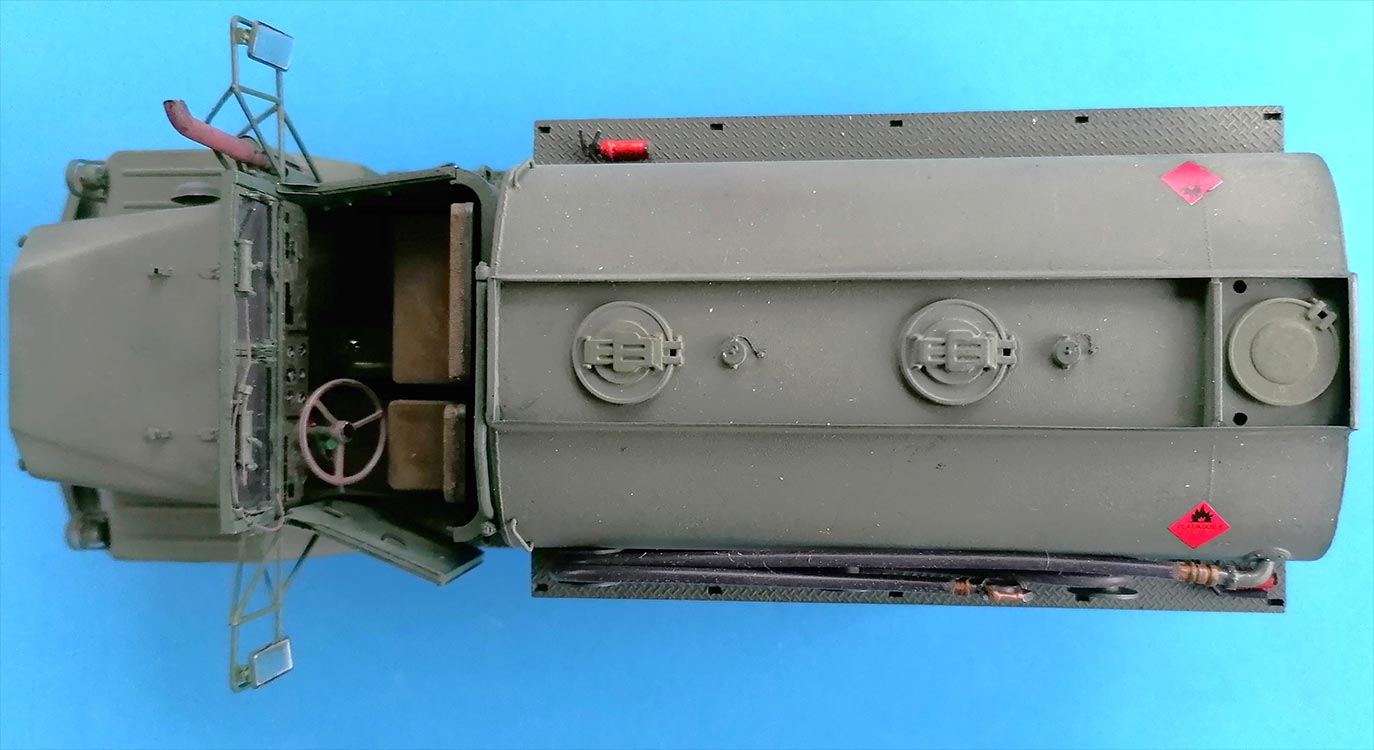
TANK:
 Before you start handling the tank parts, temporarily attach some bracing behind the tiedown eyes below the tank bed sides, as they're very delicate and prone to be bent off; the bars below the front reflectors would like to be protected similarly.
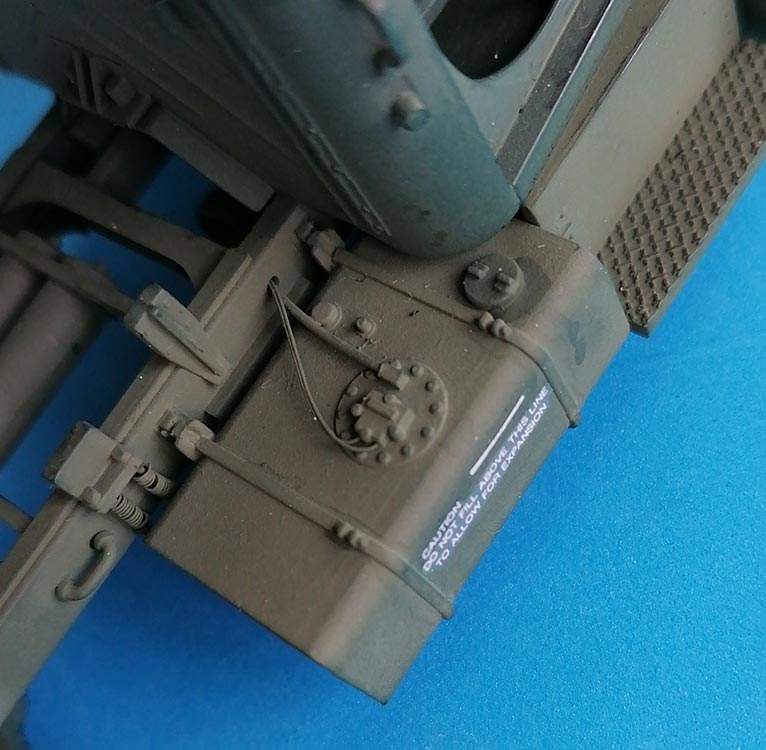
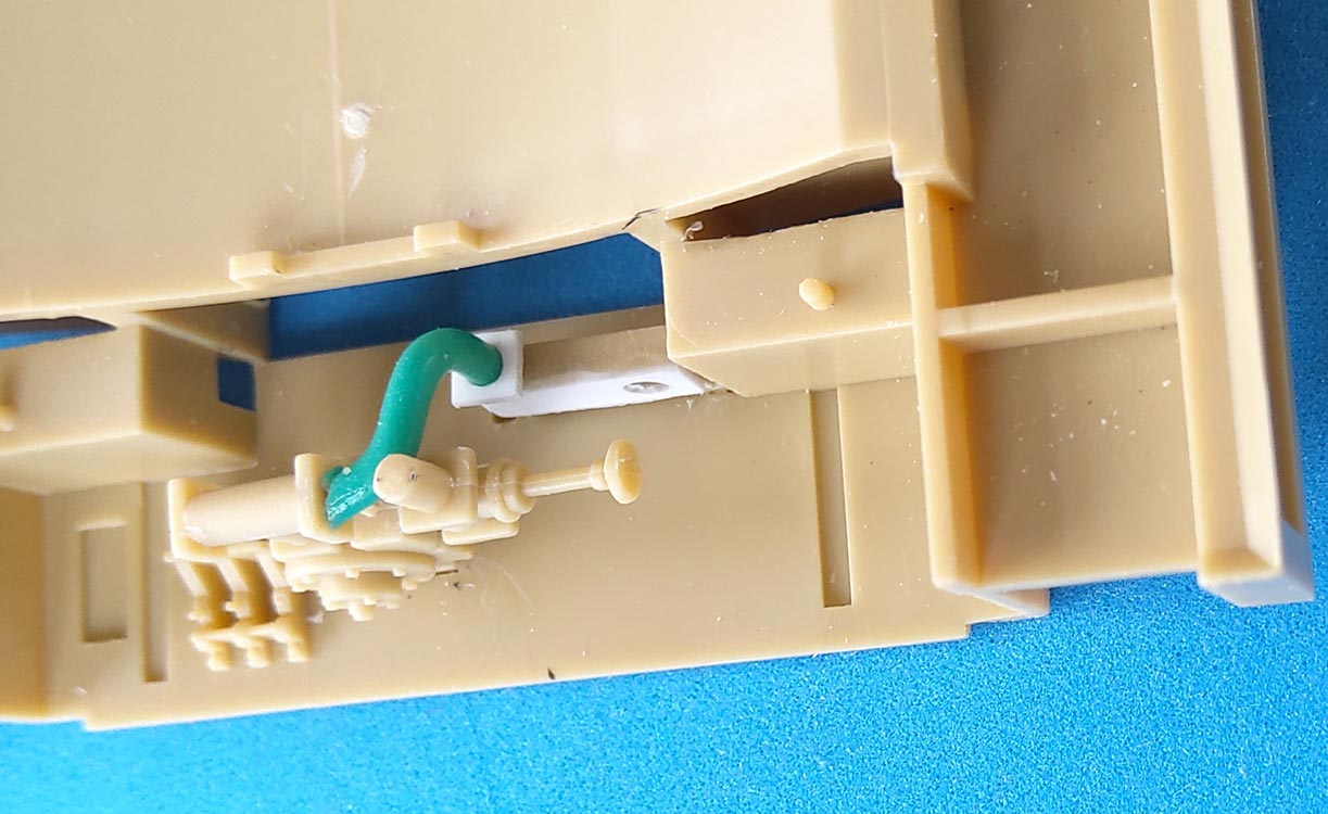
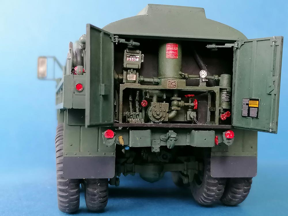
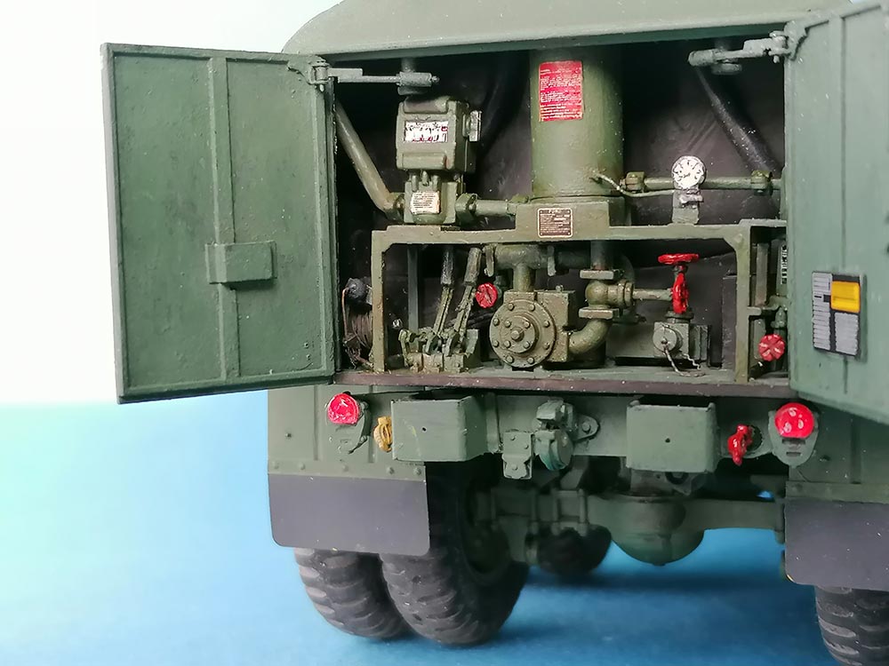
The first part to be cemented to the load bed should be C7, the tank's rear wall. Regarding the pump, Vodnik (Vodnik's M49A2C review) thankfully noted that part C48 should not lead into the tank, but into C25, so I corrected that with a piece of insulated copper wire and a layer of sheet.
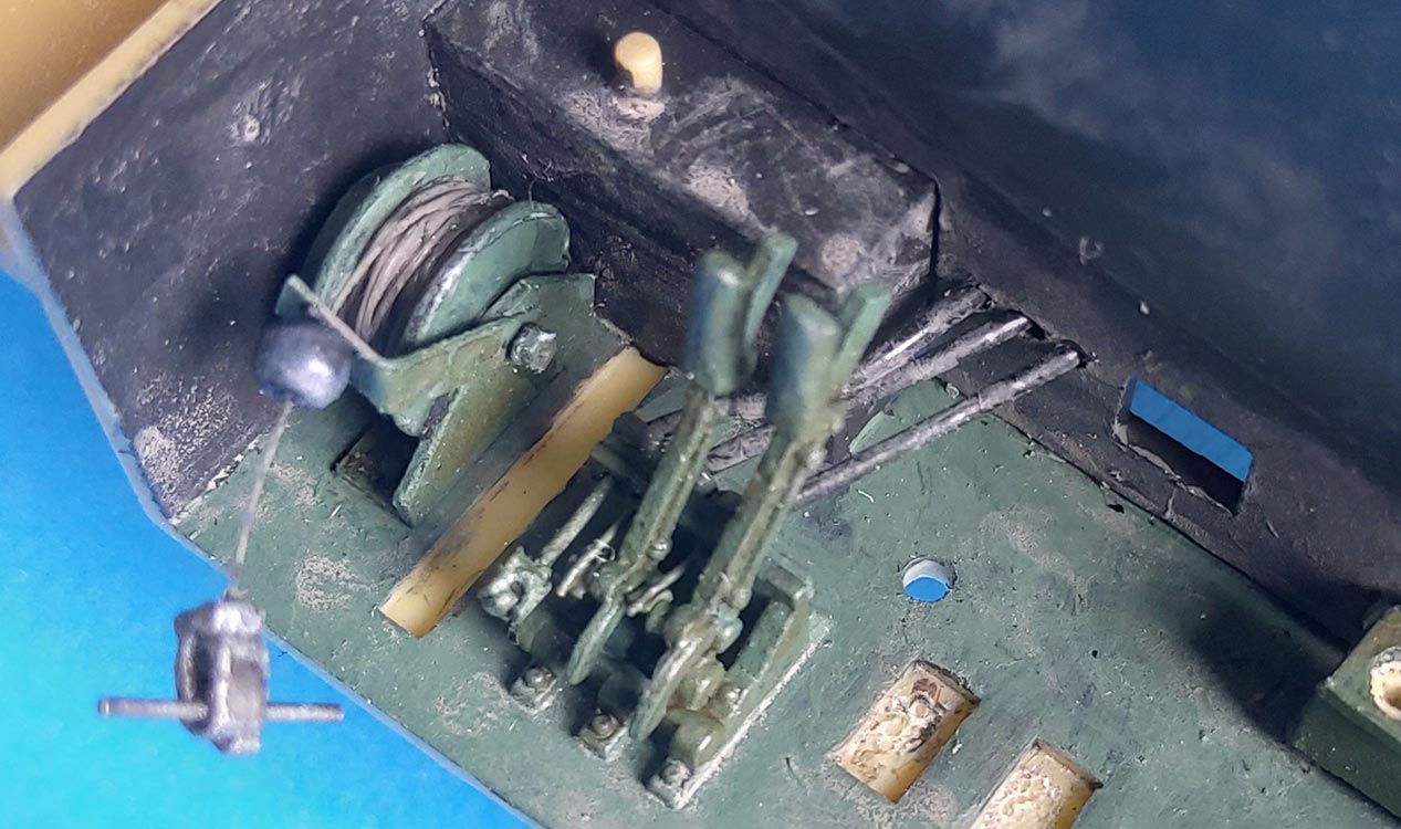 Ground wire spool C31 needed a replacement with "invisible sewing thread", while the valve control levers C30 received connections into C7 in the form of stretched black vinyl sprue. To their left, I added a "Discharge Valve Remote Control Lever" to the lever bank. The rest of the kit parts was installed per the instructions, but C22 shouldn’t just stand there, but has to be connected to C47 above it: another piece of wire to the rescue. With the conspicuous red valve wheels, size did matter: while for the small ones three crossing notches seemed sufficient, I replaced the big ones with brass parts from Hauler 35074 that were thickened with white glue. The outlet of C23 had a "securing chain" added. Pressure gauge C2 received a brass wire conduit into C33; its dial was painted black, then covered with two layers of white into which some nicks were made with a #11 blade before several coats of Future/Pledge would provide the lens.
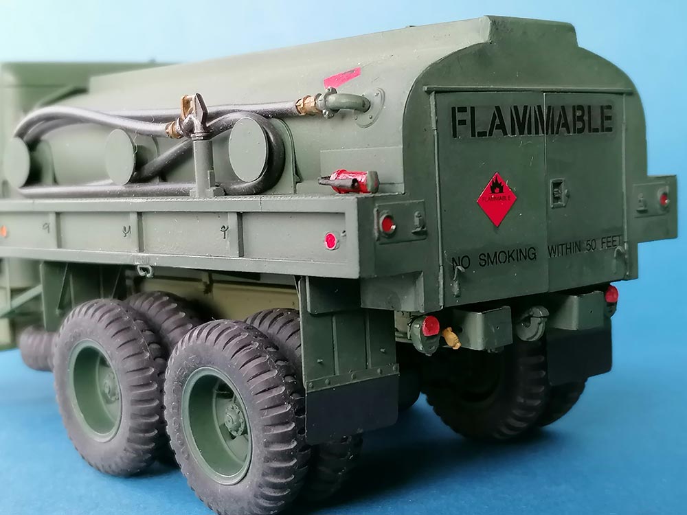
Now I installed front wall C36, supporting it with dry fitted roof C44. I dry fit C15/16, (first only one, then the other), fixed them by attaching running boards C27/28, then added cement to the sides. The tank halves needed clamping while the glue was drying, as did the whole tank after adding the roof. I added tiny securing chains to the filler hole lids on top.
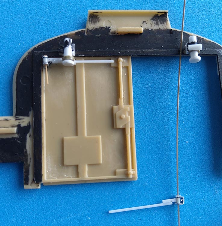 The pump compartment doors had sink marks on their outsides that needed filling. On the inside, triangle-like pieces of thin sheet were cemented over the outer corners to receive part of the hinges for the opening limiters. These were constructed from 0.5 mm Evergreen rod with pieces of thin sheet to which short pieces of stretched tubing were cemented. Stretched sprue with molten ends holds these contraptions in the sheet aluminum "U" hinges on the doors. Pieces of 2 mm rod with a 2.5mm bottom plate had "rings" of 2.5mm tubing threaded on before they were cemented to the inside of the door lintel. Pieces of stretched tubing with 1 mm diameter had their bore drilled out to 0.5mm and were cemented horizontally to the "rings". The rods coming from the doors are guided by these short tubes and secured against slipping out by a little white glue at their ends.
 Which left the main door hinges. Once again, 2.5mm Evergreen tubing was treated like stretching sprue, but with a single strand of very fine wire in its bore. This allowed stretching the tube to an outer diameter of about 0.5mm and still have a "hinge pin" inside in the form of the wire. I cut some 10mm off both ends of this hinge-to-be, but leaving the wire intact. The top segments were then cemented very cautiously into the upper corners of the frame and the center ones to the doors. For painting, the bottom segments including the wire were pulled out and re-inserted afterwards so they could be cemented to the frame. – Unfortunately, it turned out that the doors now are minimally too wide to be fully closed at the same time.
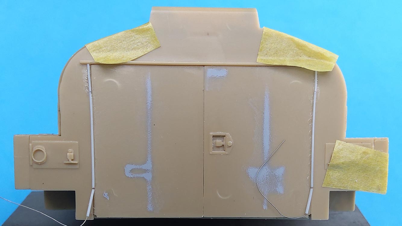
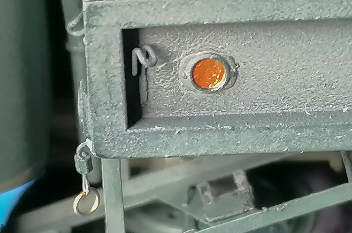 All around the load bed the molded-on tiedown hooks were removed and replaced with home made ones bent from 0.3mm brass wire. – All reflectors were treated with candy aluminum foil like on the tail and front marker lights. Below the left front wall reflector, there's a cable coming out with a nut and a ring on its end; it continues on the inside into the frame rail. This is the "Remote Control Handle": in an emergency, pulling the ring returns all tank operating levers to the closed position (by activating the "Discharge Valve Remote Control Lever", I suppose).
For the mudguards I had the Eduard parts of the old fret 35109 that didn't provide an adequate representation of the vertical stiffening ribs, so I sanded down the kit parts and deepened their ribs before I added the PE "rubber" flaps to them. Short pieces of stretched sprue were cemented to the opposite sides to represent the bolts that fix the braces. – The PE pioneer tool rack was installed with two strips of leftover PE frame.
| Painting/Weathering |
 The part of model building I plain hate – and thus am anything but good at. Games Workshop rattle can Chaos Black as primer under a Revell Aqua Color mix of some Greeen with some Dark Earth that I don't remember the ratios of led to different hues of green with the same paint at different times. Guess I simply was too old when I started airbrushing, but it just doesn't interest me enough to try and learn more.
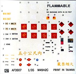
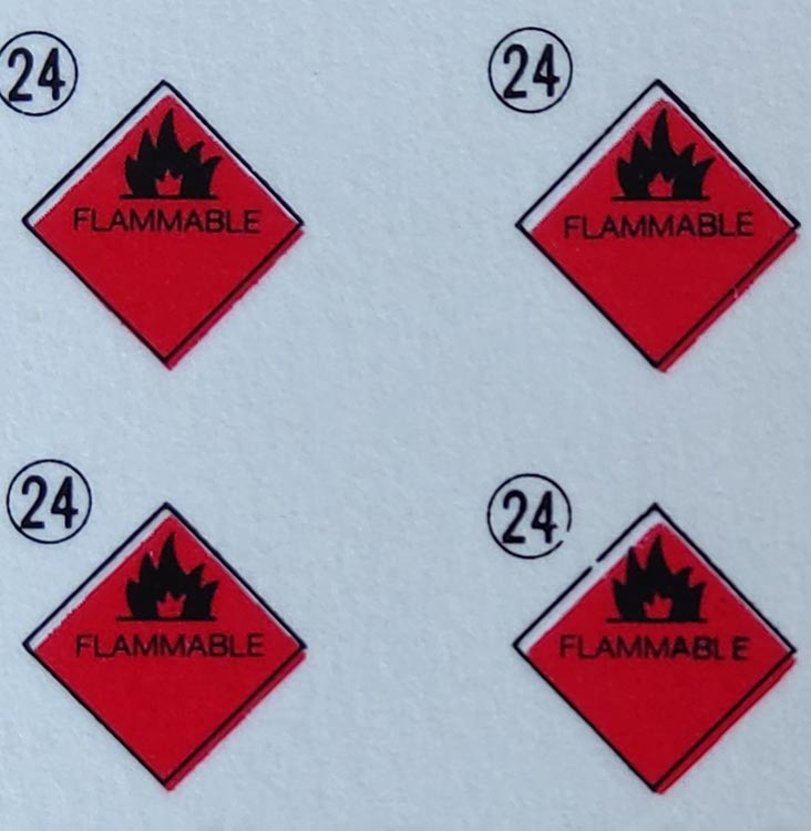
The kit's decals ("Print in Taiwan") were disappointing in that those for the dashboard were black only, those in the pump compartment illegible and the red "FLAMMABLE" diamonds notably out of register.
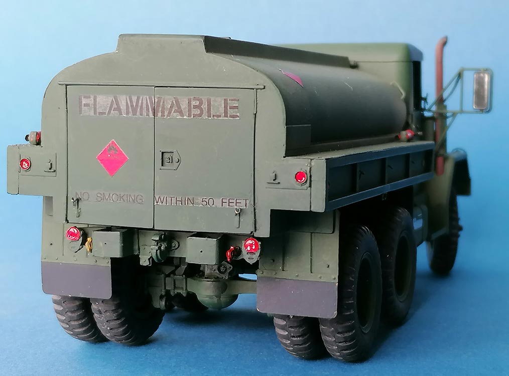
The black outside warnings on the back doors had to be cut in half instead of being supplied in two parts, and they all silvered no matter what I tried – "Sterling Silver", as it were. Plus smoking was forbidden "WITH IN" 50 feet, while the warning sign to not fill the fuel tank "above this line" was missing just that line. I dont't know yet what unit markings I'll apply – maybe it'll just become a surplus truck up for sale.
| Conclusion |
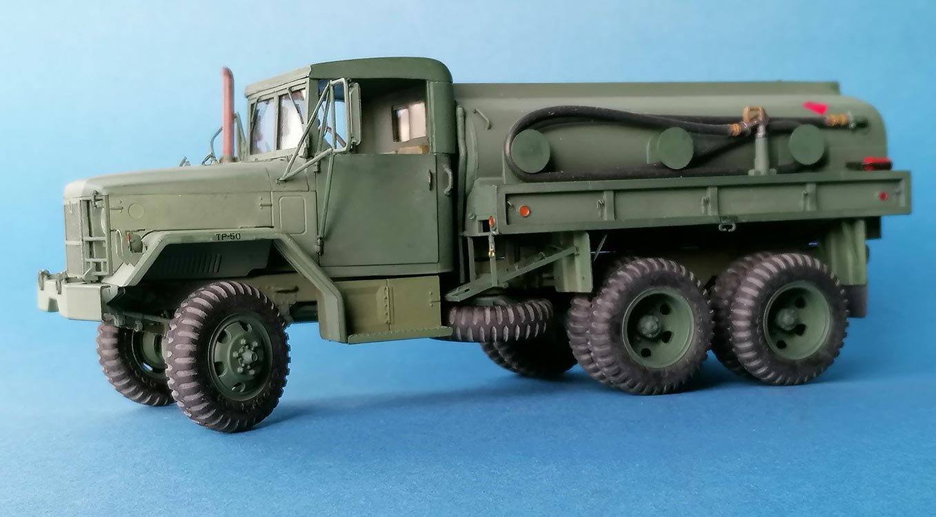
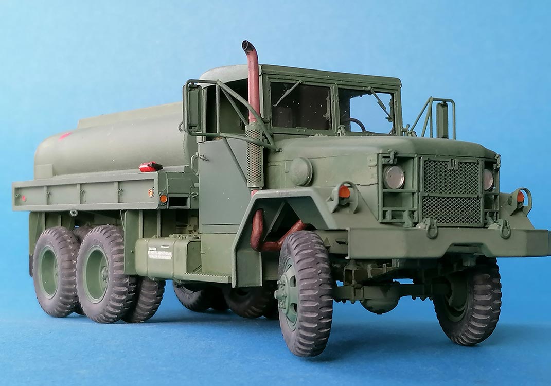
A good kit in spite of its age and some flaws, but it can sure be built and painted into an impressive model.
.
Rating:
| Price/Value: | ***** | Fitting: | ***** |
| Detailing: | ***** | Level: | ***** |
 |
 |
 |
 |
 |
 |
 |
 |
 |
 |
References:
- https://vodnik.net/references/m49a2c.html
- https://offroadcracks.com/trucks-reo-m35-a2-the-whistler-nahezu-unzerstoerbar-und-mit-unverkennbaren-sound-eine-weltweite-legende-der-u-s-army/
- https://www.svsmgallery.com/Top-level/Walkarounds/Softskins/Trucks/M35-Family
- https://www.wettringer-modellbauforum.de/forum/index.php?page=Thread&postID=905821#post905821
- https://www.govplanet.com/for-sale/Tanker-Trucks-1962-Lansing-M49C-6x6-Tanker-Truck-New-Jersey/755930/NSN/2320-00-141-8235
© 12/2023 Peter Schweisthal
5285 readers of this report since 10.12.2023