|
|
 |
| The Original |
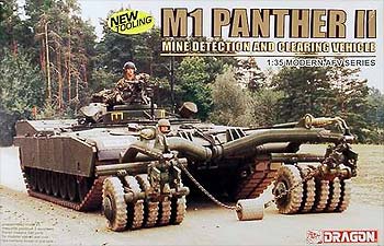
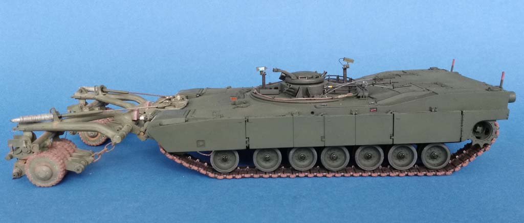
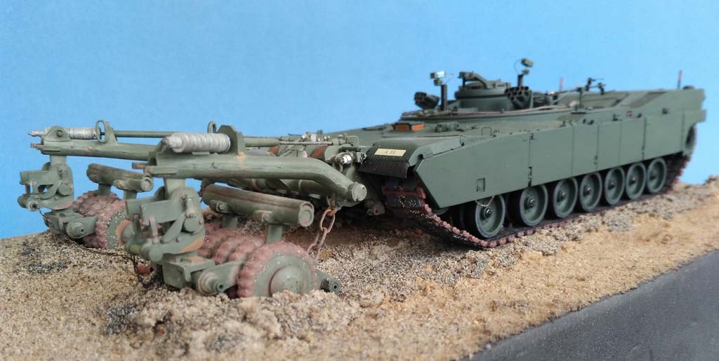
The Panther II is an RC-freak's dream come true: An Abrams tank without turret, but with a mine-roller (that had already been developed for the M 60), and the whole thing remote-controllable from more than half a mile! Judging by the small number of built vehicles, it seems that it has been less than a rousing success.
| The kit |
The positive of the experiment being that Dragon has developed a totally new Abrams hull for it.
I came by the model components in a real cheap way: A fellow modeler had bought several kits for the mine rollers only, which he intended to use on M 60 and "normal" Abrams models, and he gave away the vehicle parts. I, on the other hand, had a resin mine roller from Mini Art Studio in Hong Kong of 1994 vintage lying around that had been given to me in the last millennium for a review. A gift horse with a gift saddle, you might say. Instead of building it OTB, however, I looked around on the web and found good photos at primeportal.net and toadmanstankpictures that demanded a number of corrections and additions (sound familiar?).
| The build |
To do away with the least agreeable part of the build, I started with cleaning up the "magic tracks" and generously overlooked the fact that the guide teeth weren't hollow, as I didn't want to invest in "dental care" for a gift horse. Around the drive sprockets, however, five end connectors on either side had their "track pins" drilled out before they were cut off. The pins were replaced with stretched sprue, and the connectors mounted again while the links were placed on the sprockets, so they would move into correct positions before being cemented.
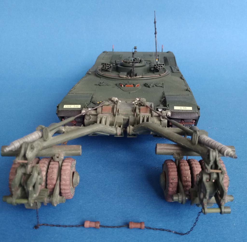
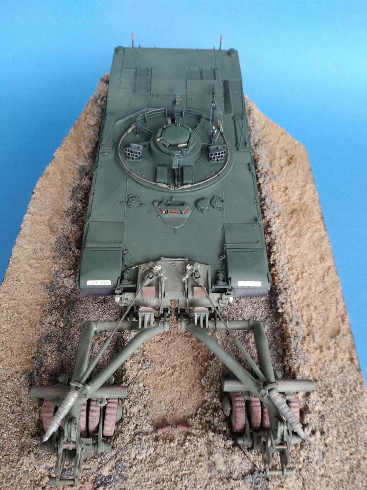
 Building the vehicle offered no real problems, but lots of improvement potential. For example, photos showed that the mine roller visibly weighs down on the tank's front, so I gave the positioning tabs of the swing arms a workover that allowed the front ones to be cemented at a pushed-in angle and the rear ones pushed out. With the two front arms, this also meant a little tweaking of the connection to the track tensioning wheels.
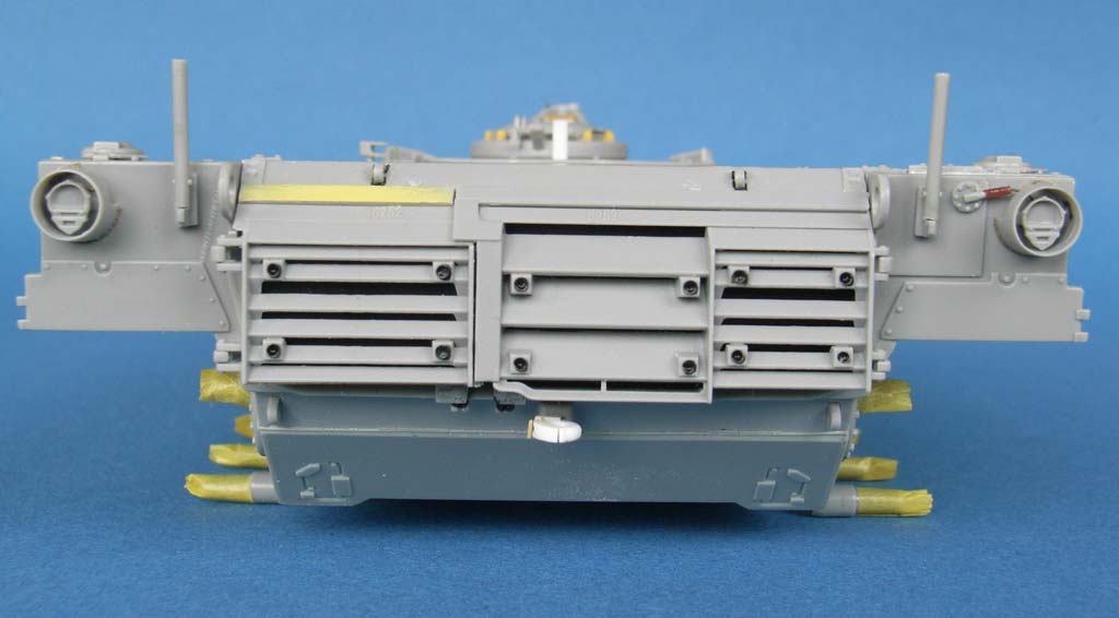
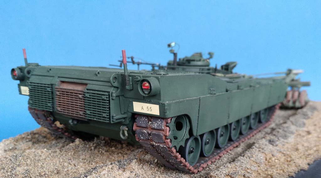
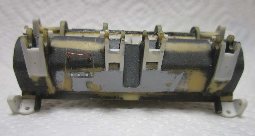
On the rear wall, the pintle was way too small and was replaced by a scratchbuilt operable sample. The protective rings around the taillights were carefully drilled out to correct their thickness and conical profile, and the electric cable on the right and its conduit looked better as separate parts than molded on. The driver's hatch "stopper" could be improved just like the wipers for his periscope, and the forward filler cap locking pin "cradles" needed slices of thin styrene to connect them to the hull. (However, I ignored that the filler on the right should sit a little more to the rear.)
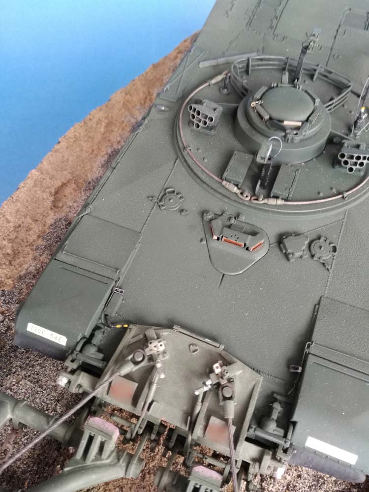
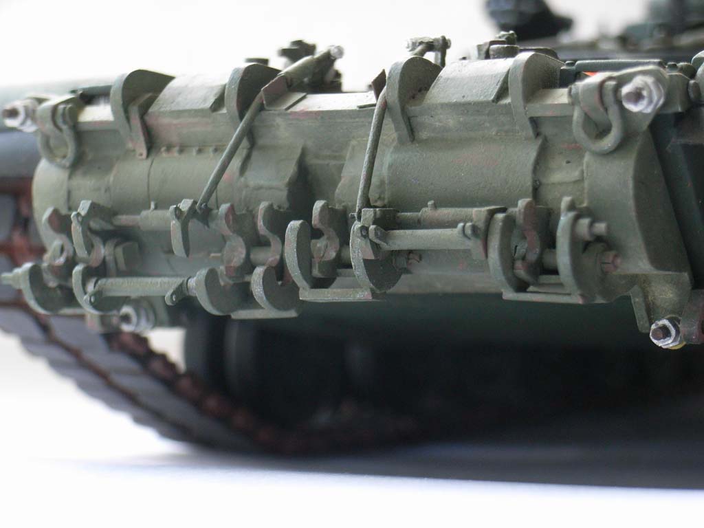
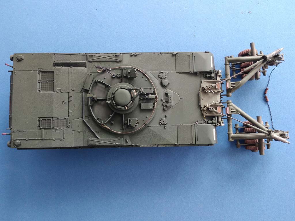
The very front parts of the track covers can be folded up on the prototype and otherwise are held down by a torsion wire. This wire and two of its arresters were molded on, the third one was missing together with the guards' hinges. The hinges were made from sheet styrene, the wire and its fittings from brass-wire and -sheet. The end connectors that serve to hold the guards in the up position came in the kit, but these parts were way too large when compared to the ones of the tracks, so a spare track link supplied connectors of the right size that had to be drilled and hollowed out. For the front mudguards, I found some thin rubber-like material. Inboard of the right hand track guard, there's the mine roller receptacle case (part G3) that needed its height doubled to later receive the respective cable. New sponson box handles came from New Tiger Model Designs.
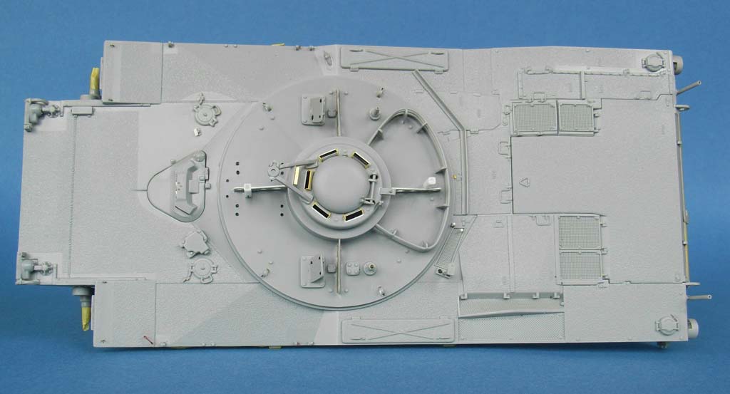
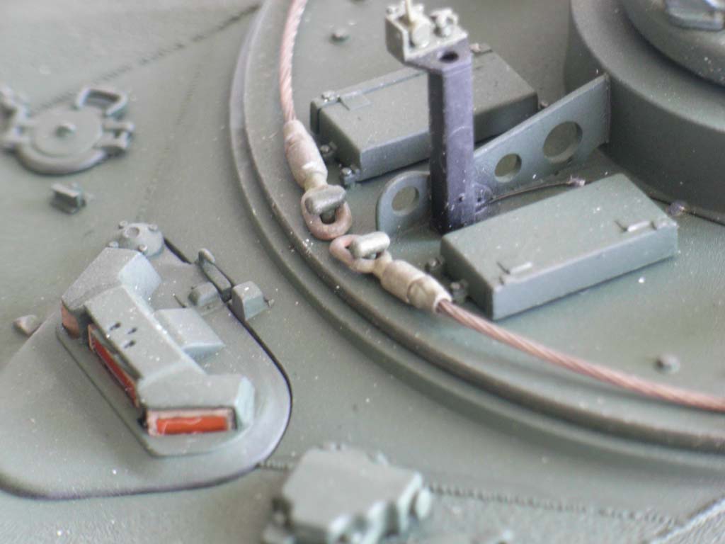
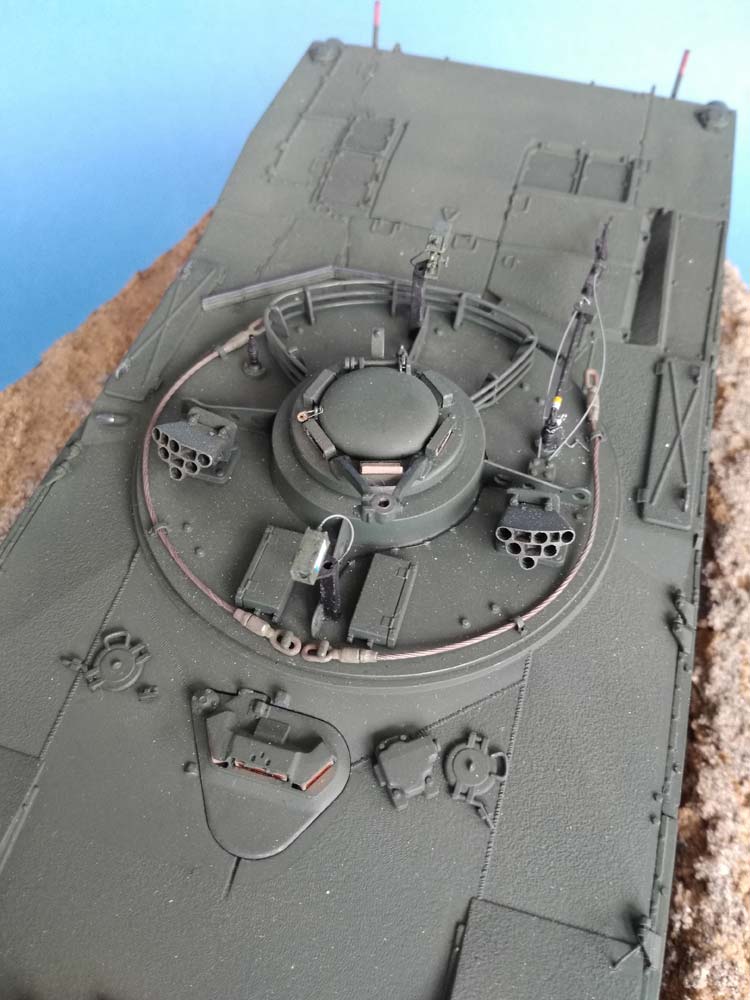
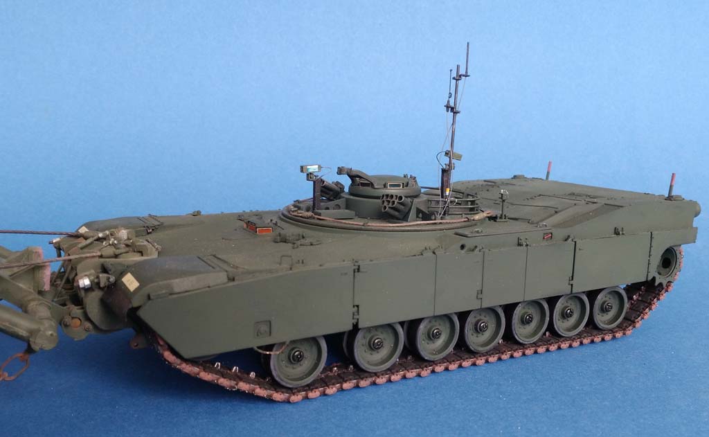
 The "turret" surprised by the front and rear braces with the camera supports on them being slightly lower than the lateral ones; besides, all braces were very thick. Sanding them down required removal of the supports, then strips of styrene were cemented on the culprits and everything was thinned. Replacement of the supports was from 2x2 mm styrene profiles, the rear one being made 2 mm higher than the one in front to get a better view behind the stern; both received holes in their top ends. It would have been better to mount them at a slight distance above the turret, to allow the cables to enter there. Weld beads and fastening bolts were made from stretched sprue. The tow cables are from annealed steel cable, their guide clamps received ABER wing nuts.
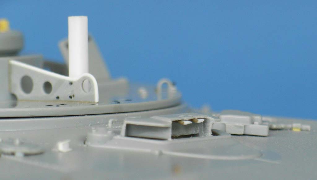
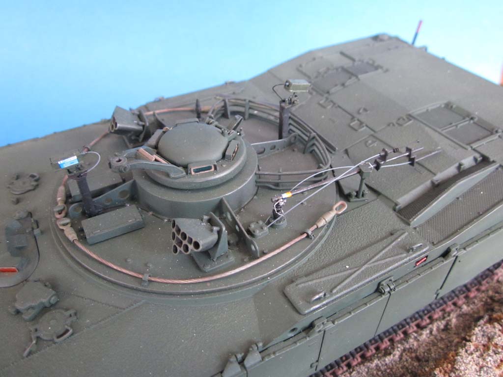
Some of the primeportal photos showed that the large antenna mast can be folded down when not in use; that was interesting (think transport damages). So, the antenna mount received a piece of sheet brass with two holes in it, and the mast got two holes through a slotted lower end. The antennae themselves weren't quite exact, either: their "outriggers" don't point in exactly the same direction, and the lower antenna had to be bent from brass wire. The cables are from stretched vinyl sprue and lead into the connection box (that received another hole on its opposite side for the camera cables). Which left the arresting pins to be constructed: 0.4 mm steel wire was cut to length and had pieces of thin rubber filament attached which came from the upper part of black pantyhose.
The camera cables are from stretched vinyl sprue, too, and fixed to the turret roof with dots of white glue. According to experts, the cameras themselves are too big. Without exact measurements, I decided to leave them off for the time being – by which time I had, however, already detailed the mounting plates, so I don't know whether this arrangement is realistic. The home-made cameras are thinner, but maybe still too long and therefore only dry-fitted. Before mounting the (drilled out) smoke dischargers, I whittled the molded-on cables in their rear to something more similar to electric leads and joined them to their respective boxes with stretched vinyl sprue. The radio antenna mount had its thick antenna cut off and a hole drilled in instead.
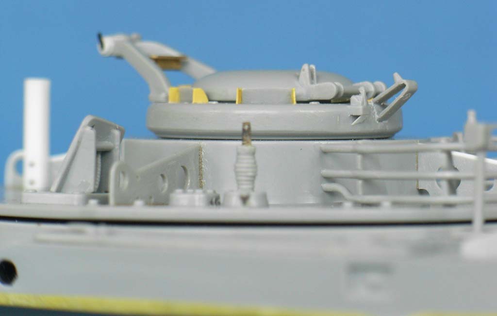
 This left the commander's cupola to be built. It is basically the one from the M 113, so no real surprises here. I detailed the hatch rest plus arrester hook and handle and added the MG cradle locking lever. My thinnest drill bit provided the holes for a padlock on the hatch. In photos, I found the PE part behind the MG to be angled at 45 degrees and painted like the periscope frames; I've no idea why. Speaking of periscopes, I found their lateral linings insufficient and replaced them from thin styrene, together with the brush guards.
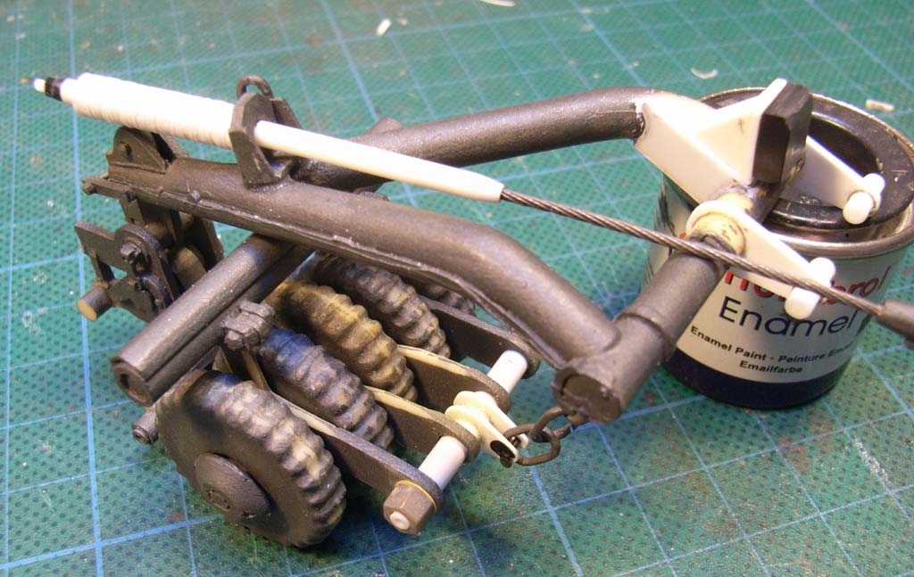
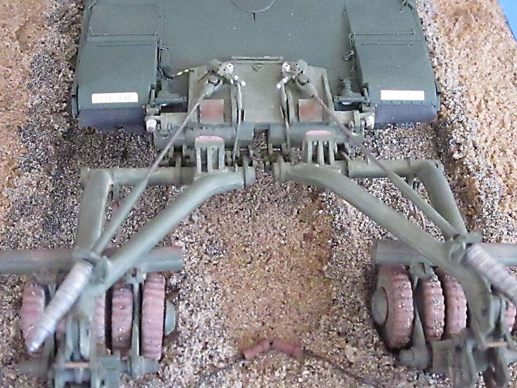
So much for the Dragon kit, now on to the mine roller from Mini Art Studio, which was used instead of the one which is normally in the Dragon kit. As mentioned above, this was already finished and brush-base coated gun metal. Owing to its age, it wasn't really correct (to put it mildly – not much info on it back in 1994), so it needed a lot of correcting work. On the lower half of the mounting unit, for instance: that was supposed to mount directly to the lower glacis plate.The lateral spacers were easy to add, but for the respective things in the center, I couldn't find photo documentation. 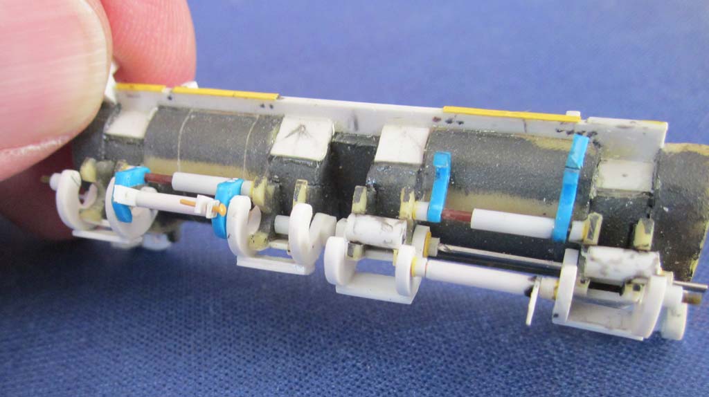 No problem as long as the thing is mounted. But as I've mounted it detachable, with bolts and cotter pins, I'd like to have the chance to show it detached, so any information would be greatly appreciated.
The amount of work needed to correct the resin kit, however, justified (as if I needed a justification!) the additional trouble of making the roller attachment mechanism operable: the somewhat warped movable resin clamps were replaced with sheet styrene, as was their operating mechanism. The "resting U's" 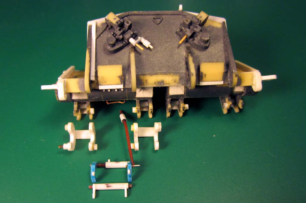 for the support ropes were cleverly cast in such a way as to allow installing the rope eyes without having to make the whole apparatus operable. The ropes themselves were made from annealed steel cable, just like the tow ropes: a pushbike's gearshift cable is 0.8 mm thick, and a broken one is available for free at any bike repair shop. If the pictures aren't sufficient, you may turn to me with your questions.
 ball pen. As for the outriggers proper and the wheels, there's not much to say, as those by Dragon appear to be better than what I had, but if you have any questions, you can contact me. As I didn't have the chain-drawn detonator for electronic mines, two "dog bones" had to do – the Panther II has been seen with these, too.
Meanwhile, DEF Models makes an "MCR M1 Mounting Base", #DM35076, that seems to be very accurate and good-looking on any Abrams, even w/o rollers.
| The painting/weathering |
 Which left the part of modeling that I plain HATE: painting. So, don't expect any lucid prose here: it was "Chaos Black" from the Games Workshop rattle can as a base coat and Tamiya "MERDEC Green" that a modeling friend had mixed up for me (thanks, Hauke!). The driver's periscopes had foil from a cookie package installed with Future, while the commander's ones were painted on their backs with white glue tinted green. The headlights had aluminum foil reflectors pushed in before receiving their kit "glasses", the taillights received pieces of red aluminum foil chocolate wrapping to their rear faces, affixed with Future. The "marker rods" at the rear are (hardly noticeable in the instructions) tricolored: bottom third black, center green, top red. The turbine exhaust grille was "rusted" with different pigments, apart from that, I left the vehicle rather clean, as I had originally wanted to do a scene with a freshly overhauled Panther receiving a "used" mine roller with the help of an M 88. The tracks had received the same black base coat plus rust and dark gray applied to end connectors and track pads.
 The roller was brush primed with Humbrol Gunmetal and overpainted with Humbrol 86, both enamels. After that, different rust tones were applied and some pastels. The spring washers and the nuts I tried to make look authentic by painting them silver and then severely dusting them with pastels. The "rubber bump stops" on the pushbeams appeared pink colored in photos, so they were primed that way.
| Conclusion |
In all, it turned out an impressive model that cost me nothing but work, while other people could have had an additional field day painting it.
Rating of just the Dragon Model:
| Price/value: | ***** | Fitting: | ***** |
| Detailing: | ***** | Difficulty level: | ***** |
 |
 |
 |
 |
 |
 |
 |
 |
 |
References:
- review on vodnik.net
- OM:https://books.google.de
© 06/2017 Peter Schweisthal
8410readers of this build log since 24.06.2017