|
|
  |
| Historic background |
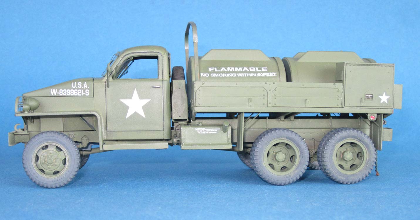
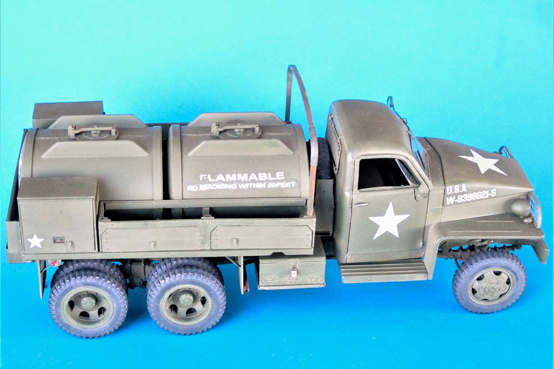
In 1941, the US Government realized that General Motors, the sole producer of 2.5 ton military trucks at the time, would not be able to supply the number of vehicles necessary for the US Army, Navy, and Marines, let alone the deliveries promised to the Allies in the Lend-Lease program. This led to Studebaker and International Harvester being included in the war effort, who both developed their own 2.5 ton trucks to the same specifications that GMC had met with their CCKW 353. To keep supply lines simple, it was decided that GMC would mobilize the Army, IH the Navy and Marines, while Studebaker would would come up with the trucks for export (and for the Alaska-Canada Highway). Studebaker's US6 model was built in much the same variants as the "Jimmy", i.e. with short and long wheelbase, with and without winch, with closed and open cab, and in countless special versions. One of these was the 750 gal. gasoline tanker US6 U5, which carried the same tank installation as its GMC "cousin".
| The kits |
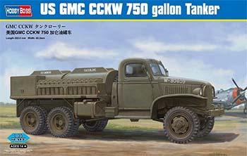
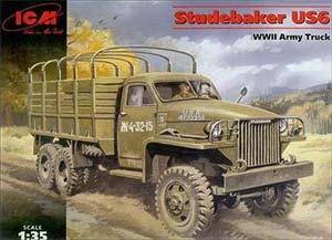
Hobby Boss has a kit of the GMC 750 gal. tanker truck (# 83830) that suffers from the same problem as all kits in their line of CCKW models, namely a cab/hood combination that has the right overall length, but split between an overly long hood/fender portion and a compressed cab. The standard solution for this seems to be a kit bash with Italeri's water tanker cab, but as I already had two unused water tanks lying around, I didn't want to go that route. ICM's Studebaker kit came to mind, which, as all rivet counters have pointed out, has a cargo bed with the wrong number of boards. However: hadn't all Studers (sic) gone to Russia? Interestingly, Hobby Boss offers one marking option for a tanker truck of the 82nd Airborne division, while CMK have a conversion set for a Studebaker tanker of the 101st AB -- that settled the issue. Originally, the tires of this kit had the wrong pattern, but ICM thankfully has corrected this since, so I was good to go.

| Building |
Something that was criticized in all kit reviews was the lack of parts numbers on the parts or sprues, so before I started, I xeroxed the page of ICM's instructions with the sprue layout to avoid having to leaf back and forth all the time.
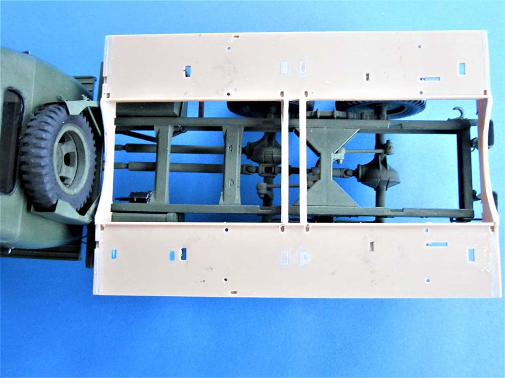
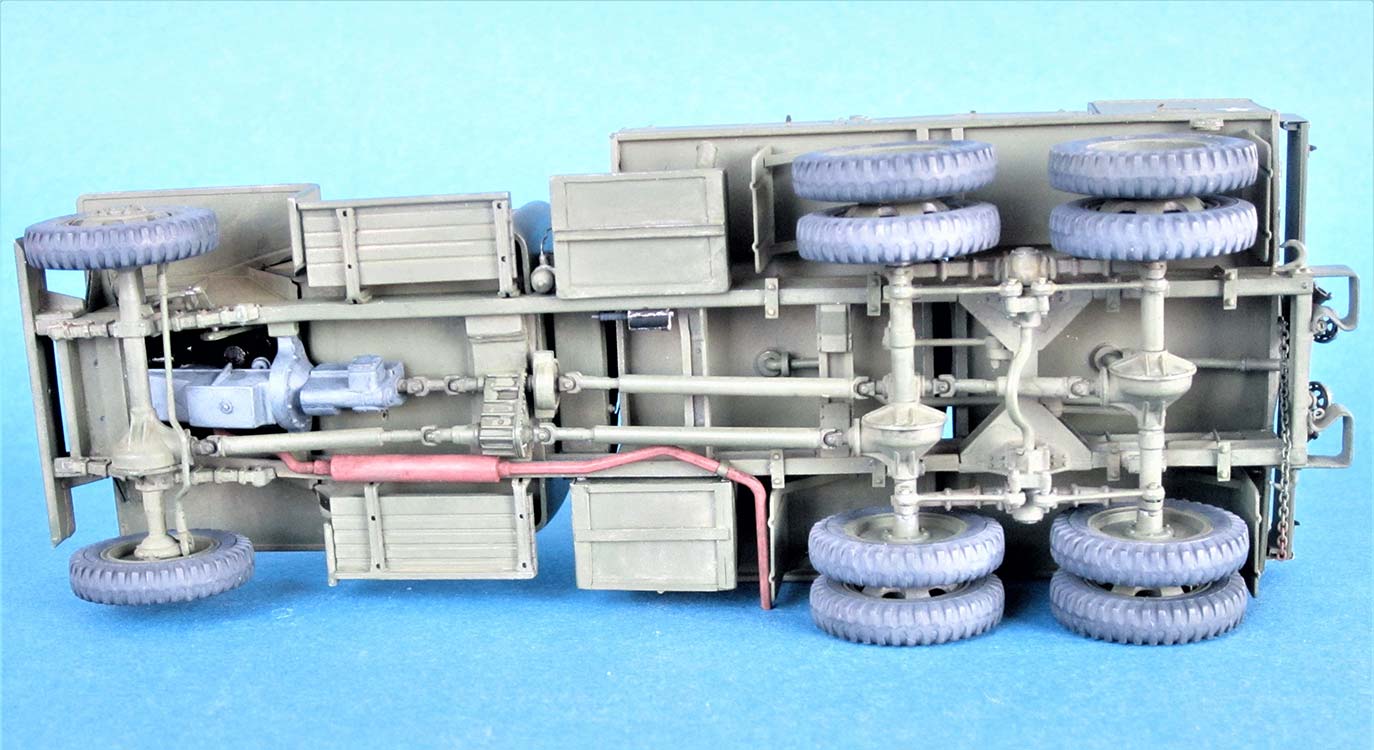
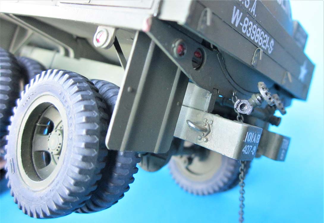
Prop shafts and axles come as one piece that was easily completed with the other parts of the drive train. After giving them brass wire valve stems, I left the wheels off for easier painting. The front wheel "brake drums" (9C) should be painted dark on their outsides, as they will be visible through the wheel rims. The chassis goes together much like HB's (or Italeri's and Heller's, for that matter): two longitudinal frame rails with a number of cross members. As all tankers had their spare wheel carrier behind the cab, removing the molded-on lever on the right was the first work order. And here's the next difference between general cargo trucks and tankers of US production in those years -- the tankers didn't have pintles, and that goes for all of 'em, CCKW and Studebaker, gasoline or water.
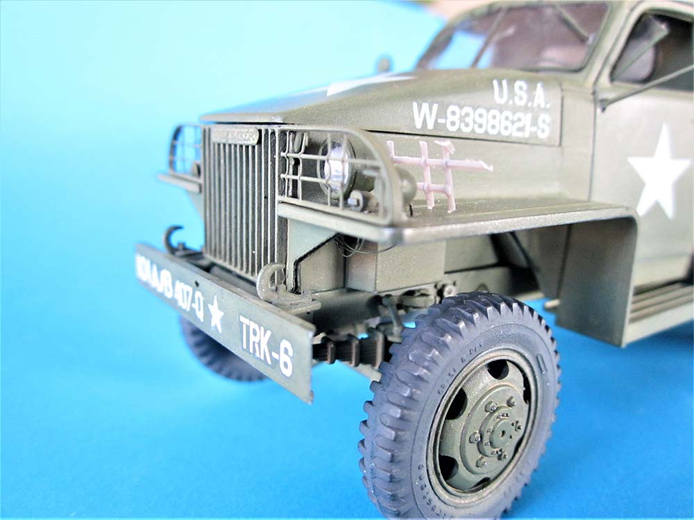
Omitting the pintle means to omit its V-brace in the frame, too. Instead, all tankers had two tow hooks, just like the ones on the front bumper, bolted to the side frame rails, where the bumperettes were fastened. Once you take a close look at them, you'll see that these hooks weren't straight, as in most all of our plastic kits, but bent sideways which, in this case, means upwards. Makes perfect sense, otherwise any ropes and such given half a chance would slip off. And these bends are on the front hooks as well, study your reference photos of CCKWs and other military trucks -- standardization. The solution came in the form of TMD's tow hooks (# 351020) that could be bent accordingly in hot water. (It would sure be nice if someone of the aftermarket crowd attended this small problem for all the model trucks out there, as Heller is the only manufacturer to ever give you these in their kit!) Standard trucks also had small eyes for trailer securing chains on the bolts holding the bumperettes to the rear frame member; I added these before I realized that they were rather senseless without a pintle... 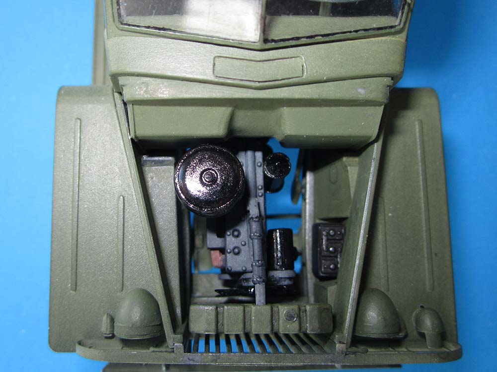
The engine went together without problems and was painted matte light gray, with some parts in gloss black and rust, respectively: as I was going to cement the hood closed, I didn't do much here. 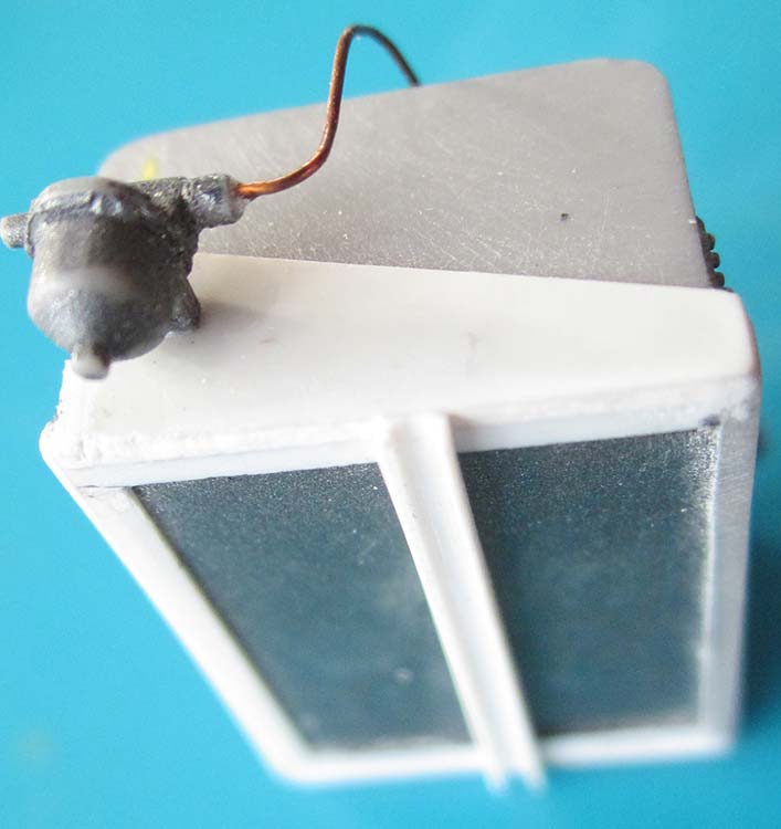
The radiator's locating pins were hard to recognize as such, so I had cut them off before I knew it and had to replace them. No big deal. -- Around the chassis, more parts were added without problems. The fuel tank needed some putty around its filler neck and had a "fuel line plus gauge indicator wire outlet" added plus two thin wires. Its rack received triangular side panels and some braces on its bottom.
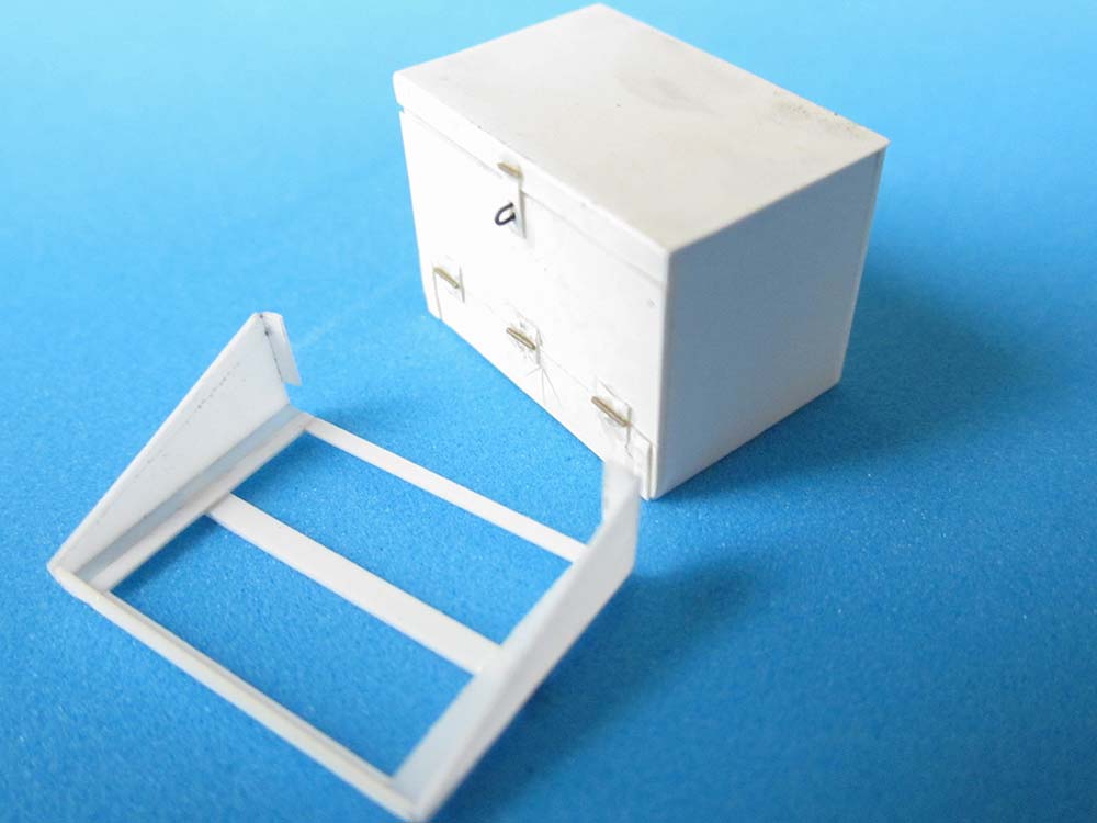
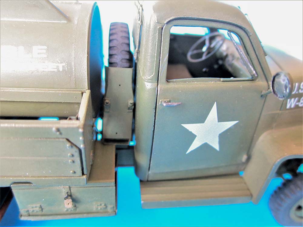
On the opposite side of the chassis, a photo in Allied-Axis showed a stowage box like the one the Studebaker tractor had, so I scratchbuilt that: The rack was copied after the fuel tank one's, and the rest after the tractor's side view in the Tankograd book. (The photo shows my first attempt which turned out too high.)
 Chassis and drive train were left separate to facilitate painting. To make sure that all wheels would touch the ground, I left the trailing arms 80A off for now and cemented the similar parts 79A to the rear axles only.
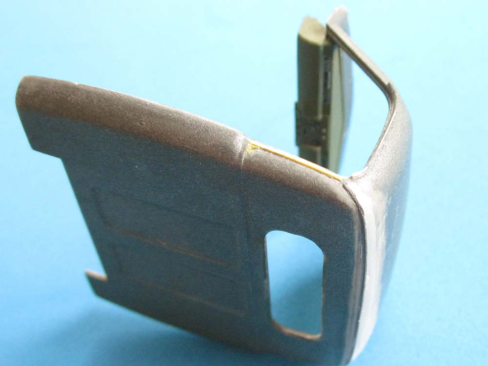
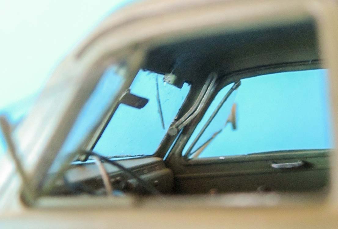
Next came the cab. Photos of the prototype's doors showed that their upper hinges go into the inside of the cowling. The kit's cowling is too thin to replicate that, so I decided to build the model with closed doors. A decision made easier by the step in the floor that results from the joint of front and rear part -- no real resemblance to the prototype here. The clutch and brake pedals' octagonal shape wasn't that obvious, either, but behind closed doors, that wouldn't matter. The seat bench received a single layer of a paper handkerchief, affixed by dabbing on thin plastic cement; the few creases I had filed in before aren't very obvious. For the dash, I had bought Archer's decal set AR35280, which later also offered the replaced three-dimensional name plate for the engine grille; here, I took the larger version, as the kit one is too small.
 In several kit reviews, I had read that cleanly joining the cab roof to the rear wall was difficult, as the seam there is rather wide. The way around this was to first cement the rear wall not to the floor but to the roof, then filling and sanding that seam. Which came off quite nicely, but didn't hide the fact that on the prototype, there's a sort of corrugation here that continues down the cab sides halfway down. Stretched sprue was cemented on a little above the seam and blended in with Mr. Surfacer 500 on its forward facing side. Luckily, there's a gap in this strengthening rib on the sides, so I could cement narrow strips of thin sheeet there that only needed to be sanded down where they meet the doors; at their bottoms, parts of the surroundings of a 3 mm-hole in sheet were added. The ejector pin mark further down on the left of the cab's rear was filled, too. Lastly, I scratch built two wiper motors that I cemented to strips of thin styrene above the windscreen's opening on the inside so the motors would show behind the windows. And above the doors, I added rain gutters from 0.4 x 0.5 mm Evergreen strip that were sanded to shape.
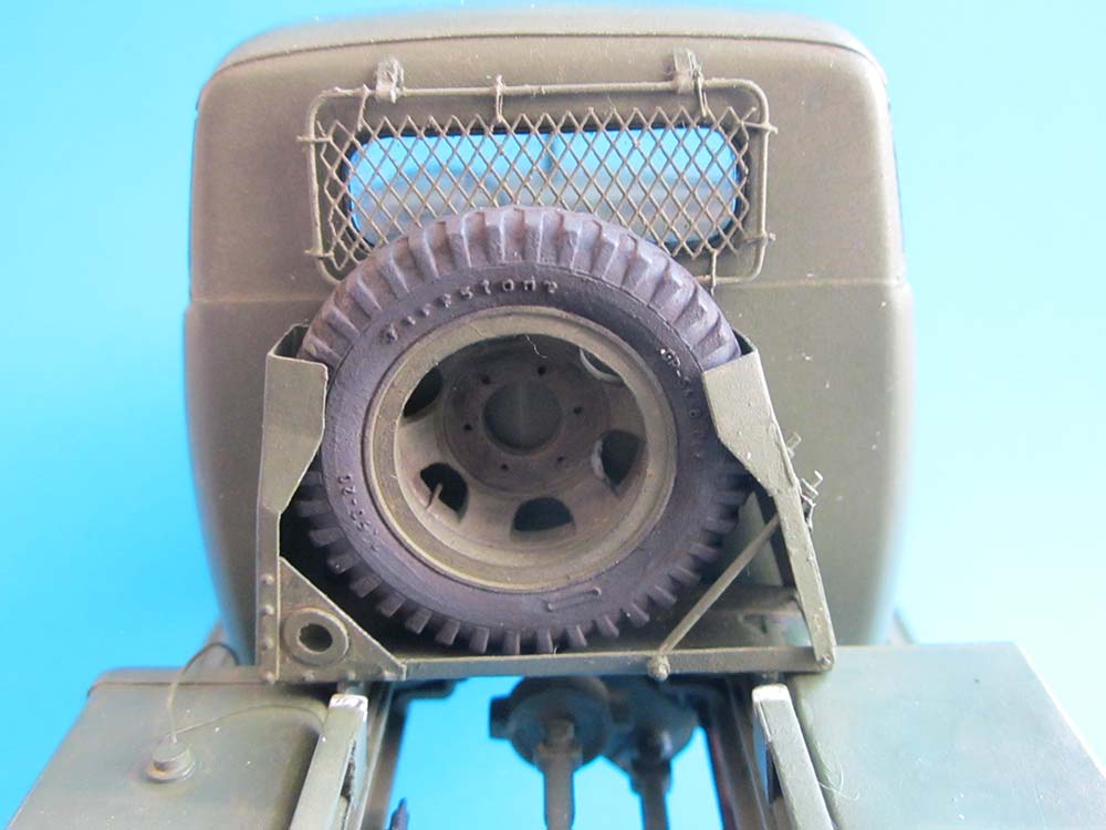
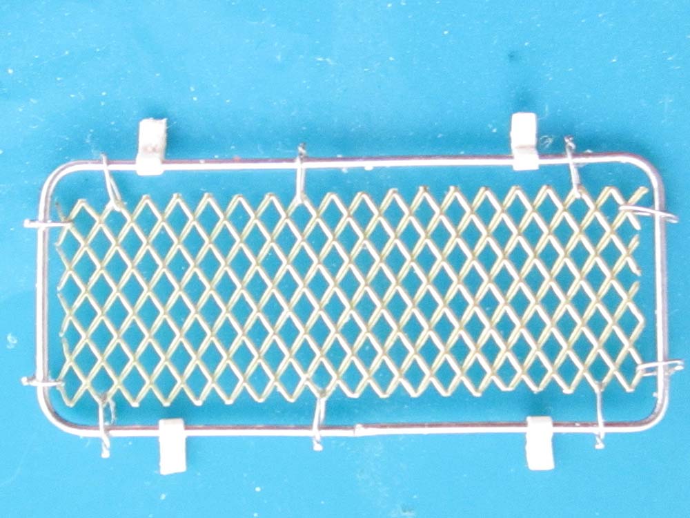 The windscreen is missing a rear view mirror and, worse, the central vertical frame brace on the inside. A piece of black plastic substituted that, affixed with white glue tinted black with water color. The "windshield adjusting arms" were sanded as thin as possible until the slots could be scratched through. The windshield itself had its frame painted black to indicate the rubber seal before it was painted in the vehicle color, new wipers were made from stretched sprue and strips of thin sheet. The rear window needed some sanding of its frame before it would fit. Its "seal" was imitated with black paint and on the outside, with stretched black sprue. It was protected with PE wire mesh that's tied to a wire frame with finest wire and mounted to the cab with very thin styrene strips.
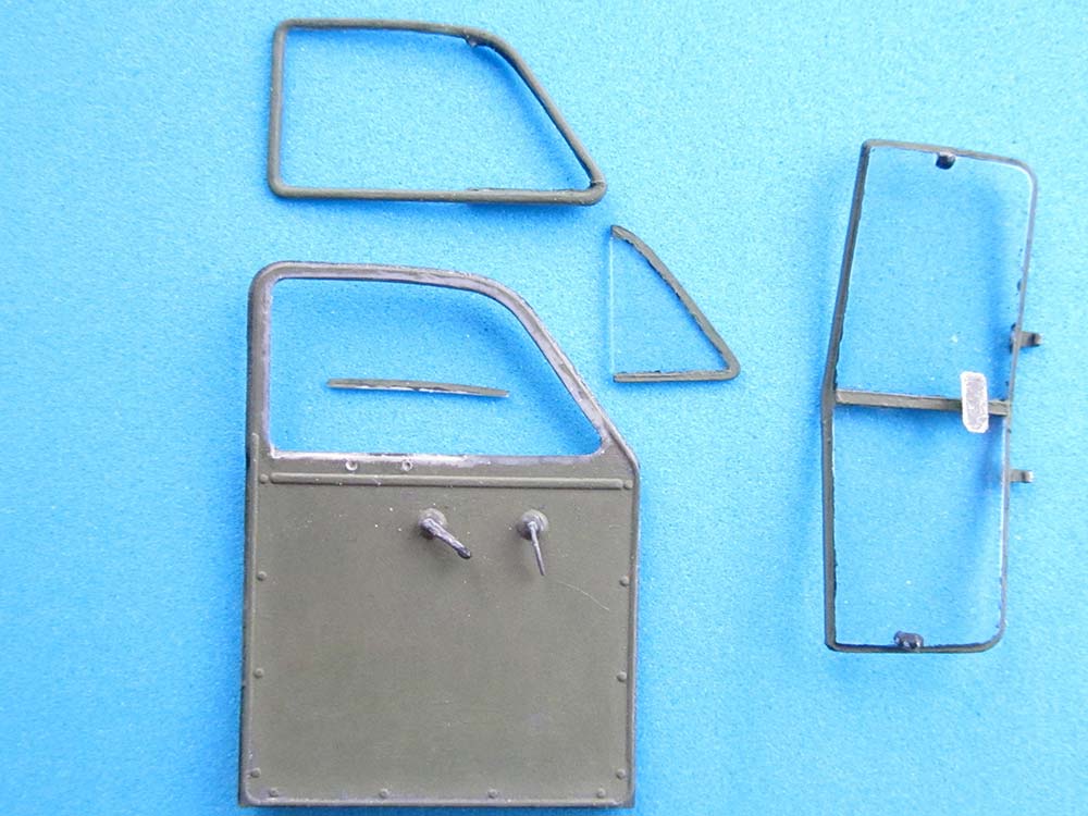 The Studebaker's triangular door vents were very special because of their hinges: Unlike those on your vintage VW Beetle, these sat not in the middle of the pane's bottom and above it, but almost directly in the front and top corners of the triangle. That made them angle out in a very special way, and I wanted to show that. The vents were carefully cut out of their frame and copied from thin acetate. Their "frames" were then painted on with first black and then olive drab, the locks were imitated with small blobs of white glue. The larger window pane had a thin metal frame that was visible at its top and where it met the vent; the kit unfortunately gives rather thick frame hints at rear side and bottom, too, where they definitely can't be seen on the prototype. I carefully also cut out these windows and removed a tiny sliver of the frame bottom, into which a 0.25 mm "window pane top" was cemented. Mounting of the vents was (much later) achieved with instant glue gel.
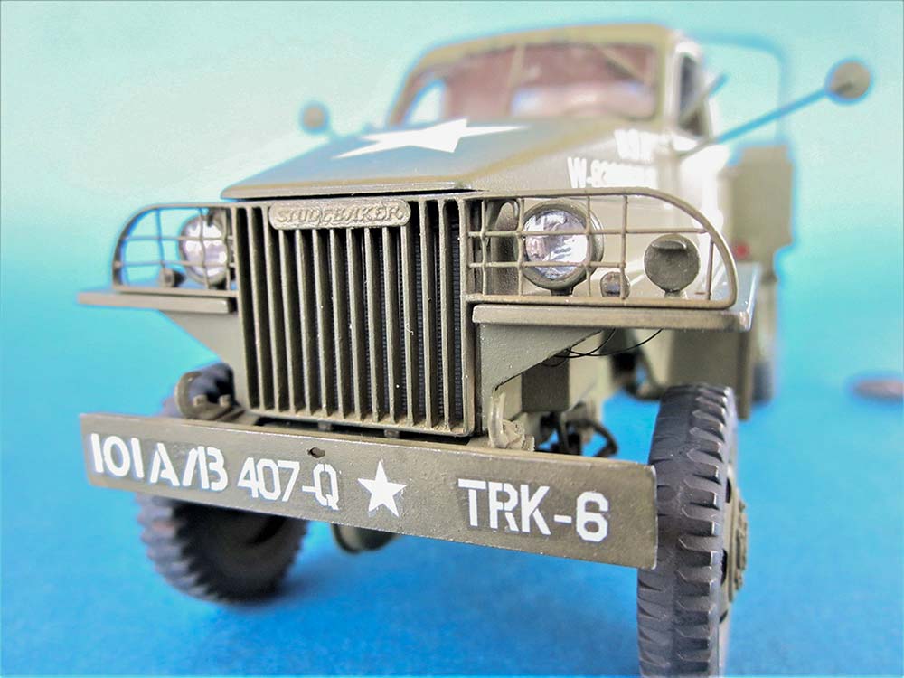
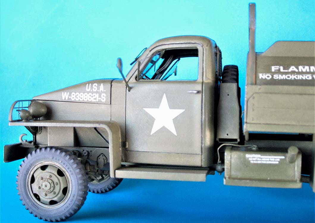
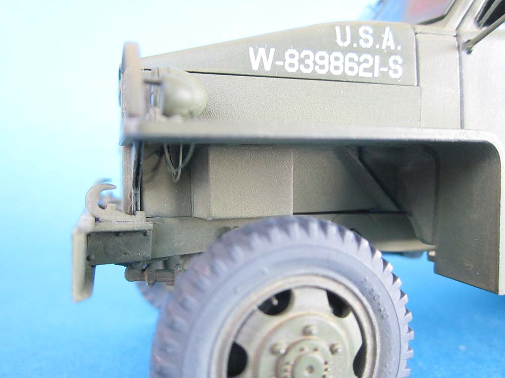 The remainder of the cowling and fenders went together without problems, but I didn't like the overly thick brush guard beams of the engine grille. They were cut out and replaced with stretched sprue after their frames had been thinned down considerably. The lights on the fenders all received "cables" from stretched sprue that was led into the hood sides. I didn't like the way the headlight lenses are reproduced: the clear parts incorporate the outer metal ring, which makes their painting tricky and the lights very long. I inserted reflectors from thin aluminum foil. Hood clamps from TMD were added at the grille's sides. The fender braces 34A had their longer "legs" shortened following the line of the triangle, as the horizontal part can't be seen behind the downward bend of the fender's sheet metal, which is lost in the kit part's thickness. And as the braces are made from two pieces of sheet metal, I scratched in a fine line.
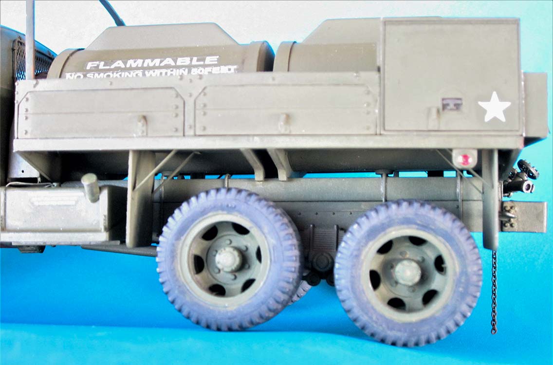
The Studebaker spare wheel carrier for the tankers and tractors looks similar to that of the comparable GM trucks, being basically a horizontal C-beam with two C-clamps at its ends. Unfortunately, Italeri have developed a rather incorrect rendition of it for their water tanker kit, and HB has copied their mistakes: Of the C-clamps, one is fixed and only the other one can be folded down to release the wheel. Consequently, there is only one support rod, and the triangular indentation it goes through is only in that clamp; on GM vehicles, that's the one on the driver's side. Studebaker's contraption opens to the passenger's side, and the clamps are straight, with a bottle profile: wide at the bottom and narrowed at the top. There are two fixing rods on the folding clamp that pass on either side of the wheel and bend into the flanges of the bottom C-beam, and both clamps stand inclined, not vertically.
 The carrier was built up from thin sheet, with all dimensions estimated after photos in the Tankograd book. My bottom trough is 32 x 6.5 x 1.5 mm and the clamps 18.5 mm high, with their lowest 11 mm at 7 mm width and 1 mm depth, the 3.5 mm at the top being 5.5 mm wide and 3 mm deep, the part in between 4 mm high with varying width and depth. The stabilizing triangles are about 9 x 9 mm and were trimmed to bring the fixed clamp into contact with the wheel at a similar angle as the "movable" one. Unfortunately, the bends in these clamps look a lot more rounded in prototype pictures than on the model, but that's modeling life. The L-shaped stabilizing rods are wire, passing through triangles of styrene strip on the clamp and adorned with plastic nuts. As the fuel tank's and the stowage box's tops reach above the chassis frame, 6 mm short pieces of C-beam had to be cemented to the frame rails to elevate the spare wheel carrier some 4 mm. The wheel had its molded-on nuts replaced by two holes.
Tanks
First off: In hindsight, I am convinced that HB based their kit on a restored open-cab truck, pictures of which can be seen between others at "Wheels of victory", see below. And that vehicle has some features (like a peculiar pintle mount and an adapter that allows two hoses to be mounted) that have been faithfully copied in the kit while they're missing in all photos of WW II vehicles.
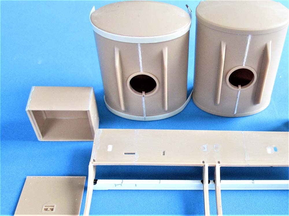
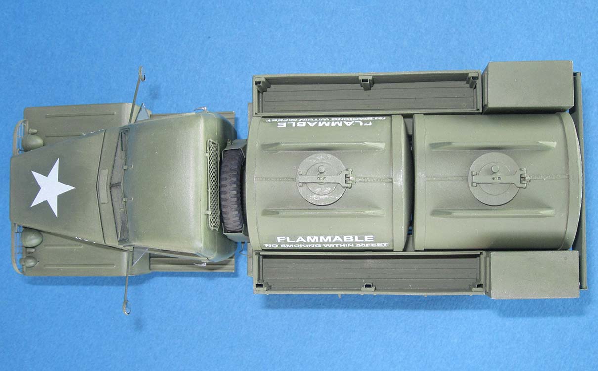
 The tank halves were a perfect fit, but had mold rims on both ends that made their "mounting bands" look uneven, so I later sanded them down somewhat and replaced them with strips of .25 mm styrene plus .9 mm plastic mounting rod. A weld bead of stretched sprue had to be added lengthwise on top, appearing to go underneath these bands. I'm doubtful whether the manhole covers are correct, as they look different in the Doyle book -- but maybe there have been two models. Mounting the tanks on their load bed proved difficult: Their radius is smaller than that of the cutouts in the support transoms, so they only rest on the very center of these braces. Pieces of 1x1 mm Evergreen strip were sanded into wedges that were then cemented on at the sides. Front and rear braces needed the "decorative strip" around the cutouts shaved off and replaced with thin sheet styrene.
Parts L16,17, the side walls of the rear stowage compartments, have a small protrusion on one corner, and on their insides, they have two positioning ridges. When you dry fit these parts on L2, they spread that part, the reason being that L2's sides are molded thicker near the rear wall, while the positioning ridges are equally long. The solution is to slightly shorten the ridges that are on the side opposite the protrusion (that represents the end of lid L4's piano hinge). Stowage bin M8+11 was left off in favor of the larger one on the frame.
 After these preparatory works, I tried to join the load bed to the chassis, only to discover to my horror that it was too long: Instead of ending a little in front of the rear cross brace of the chassis, it ended above the middle of the bumperettes. True, the Studer's long wheelbase is two inches shorter than that of the CCKW, but that couldn't be the reason for such a difference in 1/35 scale! As it turned out, HB have cheated here, again: The length of the lateral frame rails is (within normal tolerances) identical to that of the Italeri and Heller kits, but HB doesn't offer a cross brace to connect the ends of these rails! Instead, part M7 increases their length a full 7 mm, thus providing enough room for the load bed to end in front of this cross brace.
This seemed the end of the line for my kit bashing project, but then I grabbed David Doyle's book on the CCKW and started an intense scrutiny of the tanker units depicted there and comparing them to what HB has made of them in their kit. As I had read somewhere that HB's jerry cans had wrong dimensions, I compared one of them to an Italeri sample: at 14.75 mm high, 4.5 mm wide and 11 mm deep, HB differed from Italeri's 13.3 x 5 x 10.3 mm. Which made me doubt the rest, as well. The stowage rail stores the correct 13 (Italeri) cans in its 65 mm width. The load bed would have to be shortened to 89 mm to fit behind the Studer spare wheel, which left only 23 mm for the lockers that HB had made 29 mm long. Not really exact, but I couldn't be too choosey with such a poor starting basis.
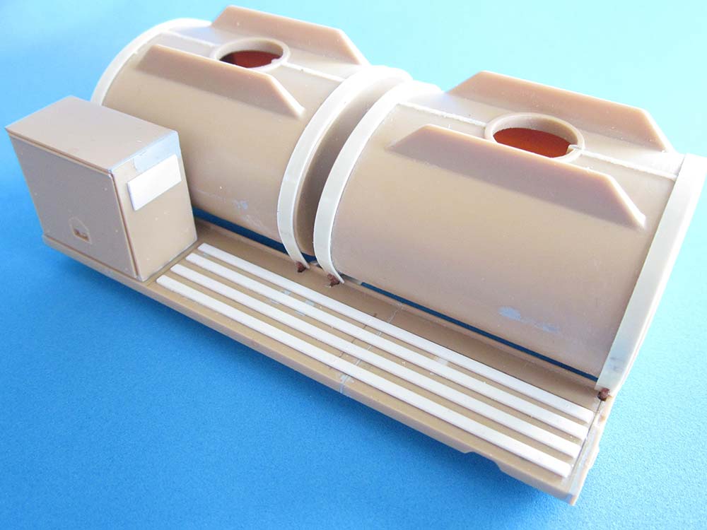
 As the bed had been shortened 6 mm (3 mm in front and behind the central transoms), each of the tanks had to become 3 mm shorter. With their manholes placed centrally, that meant cutting off 1.5 mm at each end. I did this along the securing bands, thus hiding the new seams under them. Not the most pleasant job, but I got it done. To mount the tanks, the positioning holes were drilled through and the pins at the ends of the bands cemented in. The outlet pipe underneath the tanks was shortened accordingly.
The lockers fortunately hadn't yet had their lids cemented on, which made tearing them apart at one end easier. The lids, however, had to be shortened at both sides because of the central lock, but I didn't bother to relocate the rivets on them although I made many fine cuts into the "piano hinges". -- HB's spacer beams underneath the bed weren't high enough to rise it above fuel tank and stowage box, so I replaced them with 4 mm Evergreen channel that was closed off at both ends. U-bolts to mount them to the chassis were bent from 0.5 mm rod and fixed with kit parts L14.
The lateral racks are at least 1 mm too high (their tops should be in line with the middle rivets of the lockers) and once again suffer from HB's insufficient research: There were wooden slats on the inner rails PE10 as well as on the floor. Also, it would have been nice to have the outer metal frames as PE parts, to give a better separation to their "wooden" fillets. Not all tankers had tarpaulins, so the tiedown hooks on parts L5 aren't necessary on all models. If they're mounted, they belong not on the upper, but on the lower boards, and in the center only on the rear boards, on the front ones in the rear third. For the placement of the remaining 8 hooks HB give no instructions -- they sat on the bed's front, next to the lower front corner of the locker lid locks, and four on the bed's rear. Metal channels in the racks' front and rear corners and on the center supports could receive tarpaulin bows that together with a wooden contraption on the convex end of the rear tank could serve to disguise the tanker truck as a "normal" one (although those had five bows).
 PE10 received Evergreen strips of 0.56 x 2.29 mm (HO 2x8) that were continued at front and rear of L19. Of 0.5 x 1.5 mm, 4 strips went on the floor and corresponding pieces near the bottom of L19. The inner sides of the center braces and corners of L19 first received strips of 0.9 x 4 mm, to which then tarpaulin bow channels from printer's aluminum were cemented. Their dimensions were taken from the Studebaker kit's bows, the prototype pictures found in David Doyle's book.
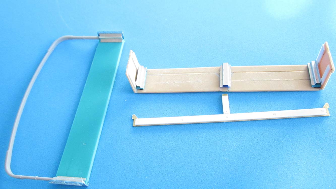 This book also showed what the "bow holder" on the rear tank had to look like: as high as the lateral racks, three boards with metal fittings at the sides that are mounted to the lockers and have bow channels in the corners. A styrene "board" of 0.9 x 11 x 61 mm received two separation lines inscribed and sheet aluminum ends with Z-bends (1-4-1 mm) and channels in their corners. Mounting to the lockers and the boards with 4 white glue "bolts" each.
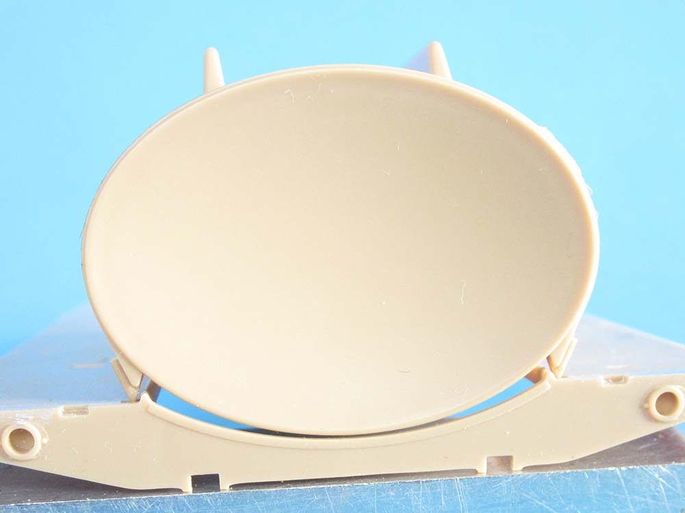
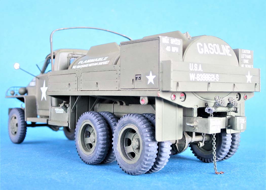
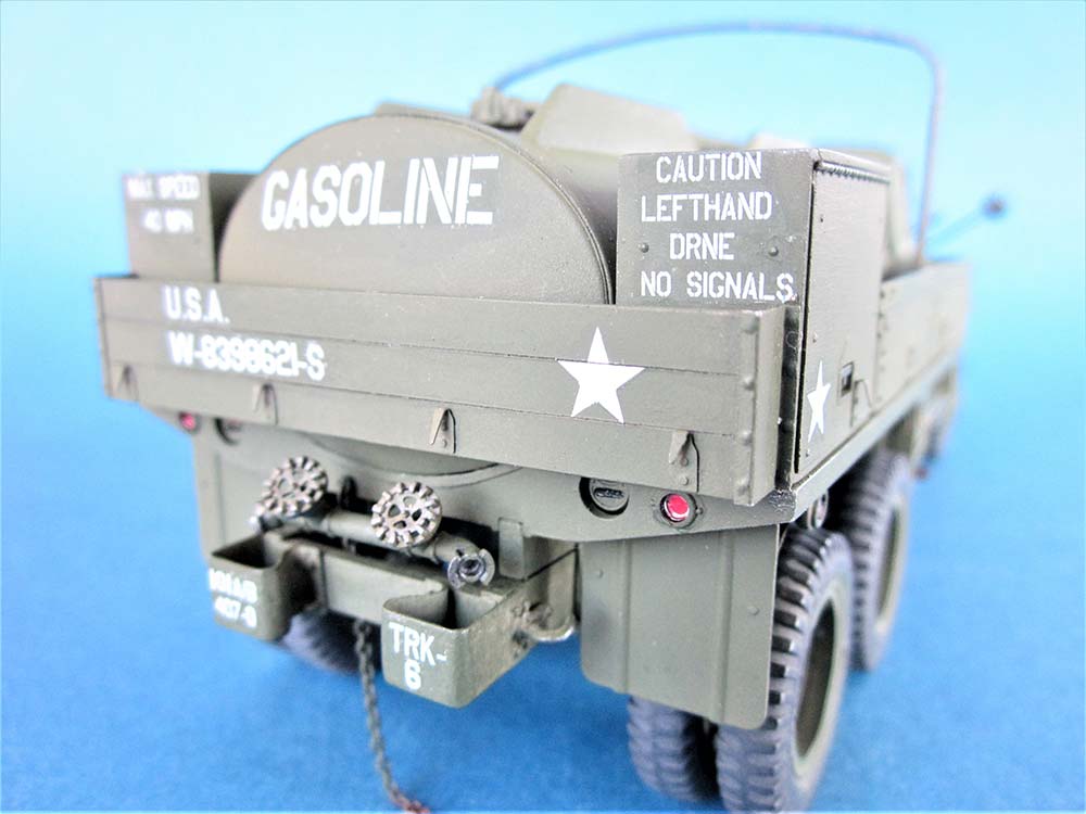
US military vehicle tail lights have traditionally been too complicated for kit makers to correctly reproduce: On the left, there's a red oval in the upper half and a slot beneath it. The lamp face on the right has that oval visibly filled with sheet metal that has a narrow slot, and below this, there's a slot like on the left. The red oval is the "service tail and stop light", whereas the three clear-glazed slots (that appear just somehow dark from a distance) cover different blackout lights with little reflectors. With parts W2, HB have created two identical fantasy lights that look rather well like the upper part of a right hand light but offer plain ovals at their bottoms. (For completeness' sake: what ICM has molded into the load tray's rear transom are two identical things without any resemblance to the prototypes.) Years ago, I've made castoffs from corrrect model taillights, so I had no problems here. -- For the reflectors, I took thin red aluminum foil from chocolates and placed it behind the kit supplied lenses, affixed with Future. The mudguards received sheet aluminum braces.
The fuel outlet is another detail that HB copied from the wrong vehicle, as the wartime photos invariably show only one tube/valve, going down at an angle. Unfortunately, I've been unable to find photos that would've allowed me to construct the correct gizmo, so I mounted the kit parts, but with white glue only so I can change this if and when I find the necessary information. -- As static electricity can lead to disaster with gasoline tankers, these vehicles dragged a piece of chain behind which I also added.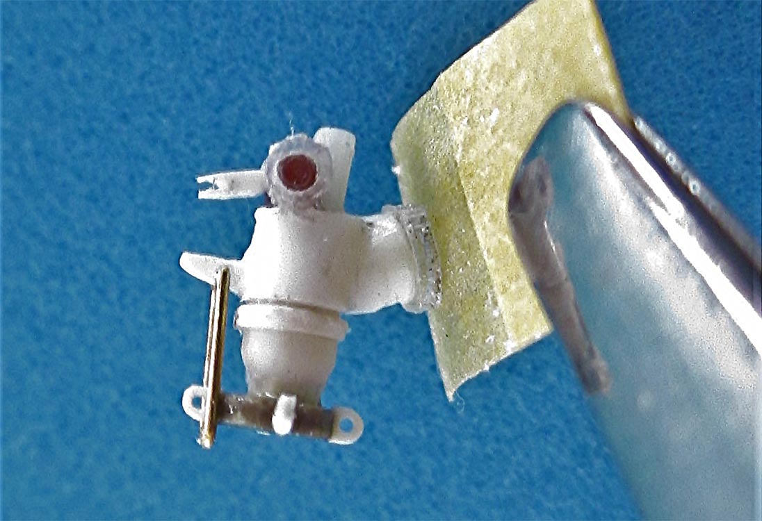
Supplement
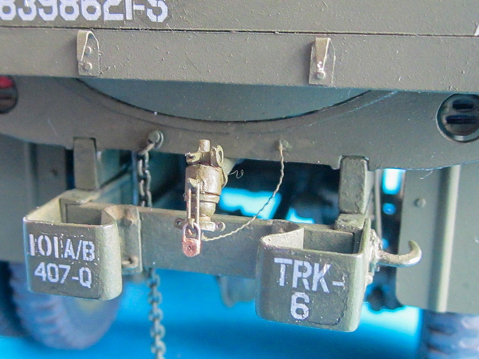
As I had hoped, eventually pictorial evidence turned up that allowed constructing the Discharge Faucet as it should look: The cutaway drawing from TM 9-1801 gave the basics, and with its aid, the photos in the Doyle book could be interpreted in totally new ways: shades and tonalities suddenly made sense, and conclusions could be drawn where photographic evidence was missing. I don't claim to have created a perfect replica, but my version is certainly much closer to the original than what the kit contained.
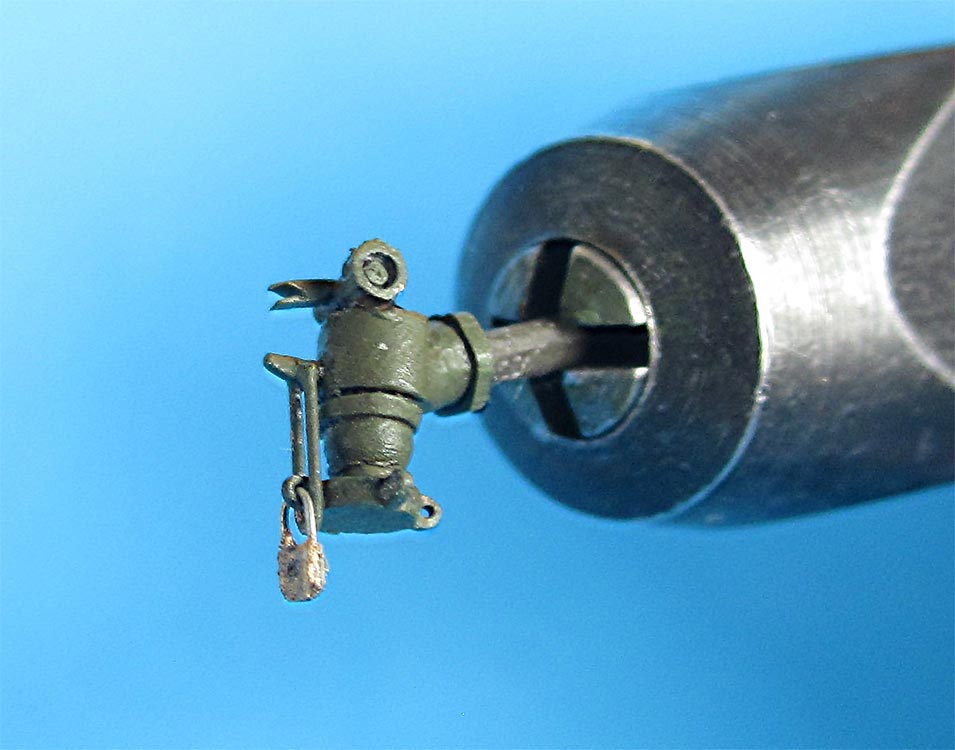 Faucet
My dimensions: overall height 6.7 mm, diameter of the top spring housing 0.9 mm, of the locking cap (like you find at any heating oil tank, plus securing chain) 1.7 mm. Hasp L in the drawing is going over one of the four eyelets of the cap, to be secured by a padlock. I gave hexhead nut C a diameter of 1.2 mm, its axle 0.6, and the connection to the tanks' discharge tube 2 mm. Further dimensions resulted from converting of what the drawing showed.
And according to TM 9-2800, the two tanks should each be 54 inches wide and long, which in 1/35 would be 39.18 mm, while in the kit, they're 42 mm long, so their base and the chassis had to become too long, too.
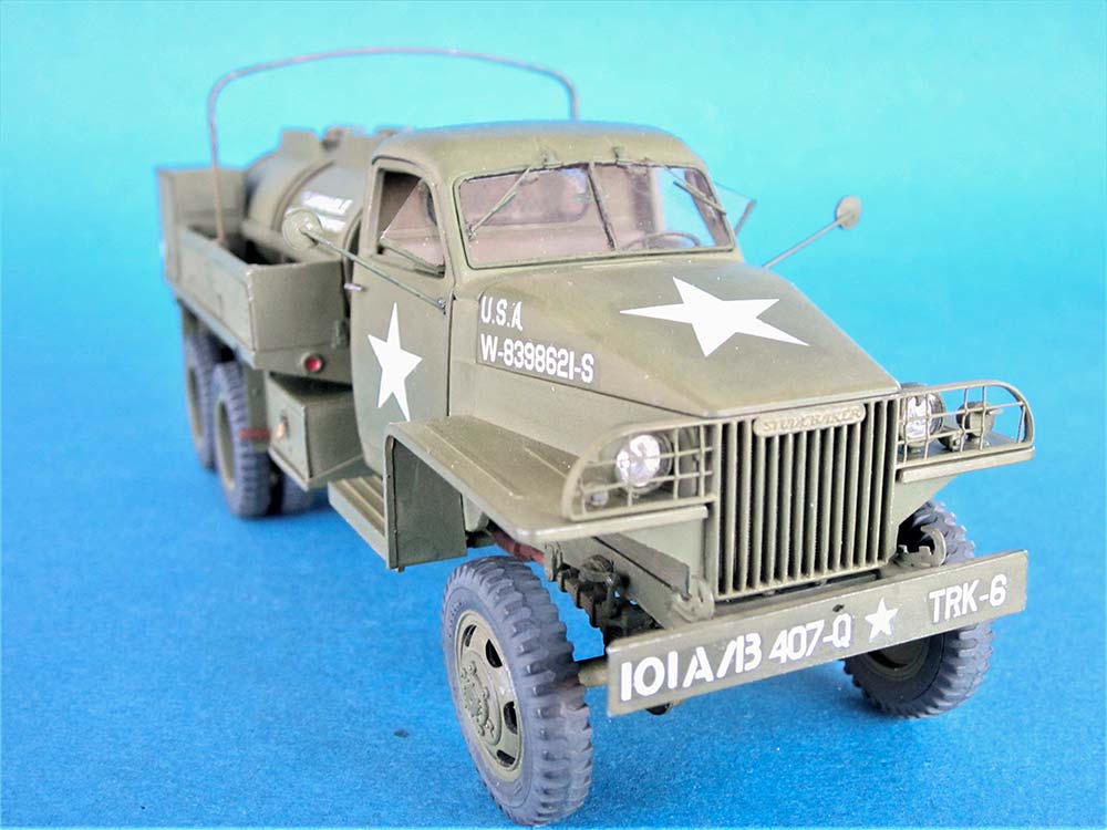
| Painting/Weathering |
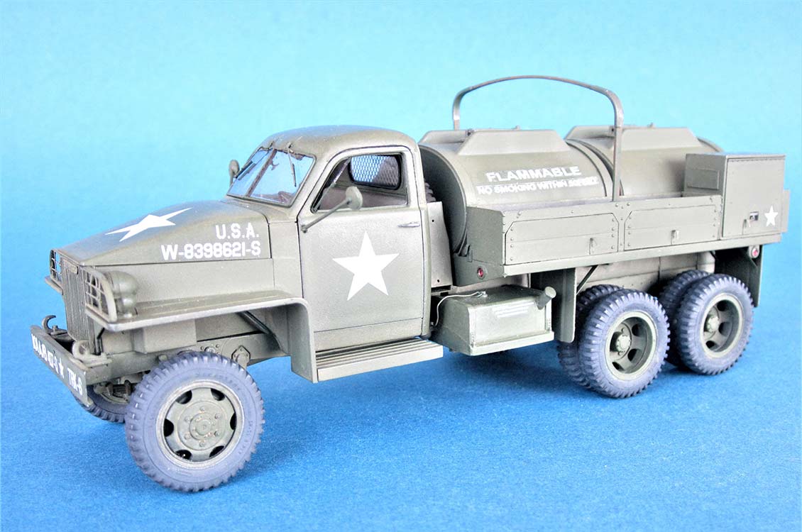
Aaargh -- the part of modeling I plain dislike, and the paints sense that and fight back. I primed everything with Humbrol 53 Gun Metal and then sprayed a mixture of Revell Aqua Olive Green and Dark Earth. For markings, I tried to imitate what CMK offered with their conversion kit, but deviated slightly because of my tarpaulin rack. I've no idea if a vehicle with this registration ever existed, and frankly, I don't care: I'm not building for a history museum, but strictly for my pleasure, and I'm content with the result, although I goofed somewhat with the markings on the front tank. And I only noticed HB's warning of "lefthand DRNE" and "do NET fill above..." when I took the pics.
| Conclusion |
A kitbash of two kits from different manufacturers. It worked out rather well, but was anything than an Operation Shake 'n' Bake. Starting with the ICM Studebaker, I found no real problems fit-wise, but there were a number of details either not well reproduced or missing at all. Overall I found it somewhat below today's standards but with sufficient potential to build a good model from it. Hobby Boss, on the other hand, offer a product with lots of problems that can not be remedied without severe surgery or even total replacement, like the wrong length of the chassis -that also carries forward to the tanks- and especially the cab with the overly long hood and compressed driver's compartment. Detailing of the chassis and drive train are very good (but there's no drag link for the front axle), the lateral stowage rails are too high, parts fit is fine, the gas cans have wrong dimensions… In short, this kit is way below what we can expect nowadays, but the only game in town until a better rendition of the gasoline tanker comes out. Plus the chassis can be used as basis for conversions.
ICM Studebaker:
| Price / Value: | ***** | Fitting: | ***** |
| Detailing: | ***** | Skill level: | ***** |
Hobby Boss GMC gasoline tanker:
| Price / Value: | ***** | Fitting: | ***** |
| Detailing: | ***** | Skill level: | ***** |
 |
 |
 |
 |
 |
 |
 |
 |
 |
 |
 |
 |
 |
 |
 |
References:
- Tankograd Technical Manual Series Nr. 6037
- Allied-Axis Nr. 21
- David Doyle, The GMC CCKW Truck in U.S. Service, Squadron/Signal 2013, ISBN 978-0-89747-724-6
- https://www.youtube.com/watch?v=ZZaEVBtyDfg
- https://www.scalenews.de/studebaker-us6-walkaround-33/
- http://www.wheelsofvictory.com/Gmc%20Gasoline%20tanker.html
© 05/2020 Peter Schweisthal
6987 readers of this build log since 17.05.2020