|
|
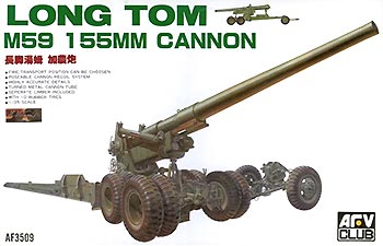 |
| The Original |
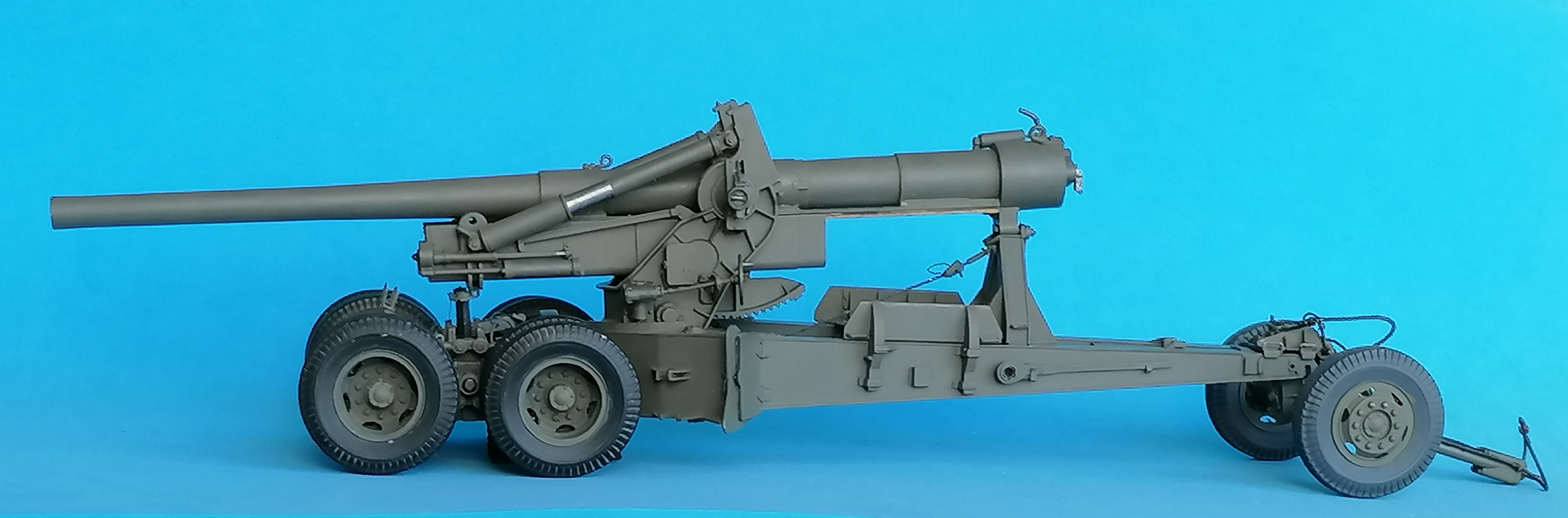
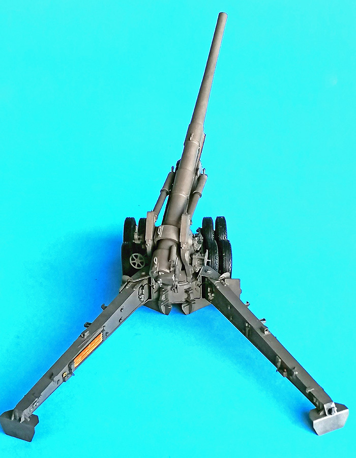
The "Long Tom", as the 155mm Gun M1 was nicknamed, was used by the US Army and allies during the Second World War and afterwards and also delivered to a large number of friendly nations. After the war, the original limber M2 was replaced by limber M5 and the gun's inventory number was changed to M59.
| The kit |
I bought this kit in late 1994 and, instead of building, scrutinized it and all available sources and TMs. Bummer, as it turned out that the gun tube was too short and had a too thick rear half, and that the limber would not allow a realistic way to hook the piece up to any prime mover. So, into the stash it went, and it wasn't until after I had built the AFV Club and Tamiya models of the M40 "Long Tom as Self Propelled Gun" that I dug it out again, hoping that I would find solutions for its many problems. (AFV Club eventually reacted by releasing kit #35295 of the WWII M1 with limber M2 and many of the errors corrected, – but leaving the faulty sprues A,B,C and adding correct parts only where AFV thought necessary. So, a number of the following observations could also be useful for a build of the newer kit.)
As for the carriages (that were also used for 203mm howitzers), it seems that the tires and wheel rims of these guns differed – roughly speaking, between 6-hole rims with civilian tire tread for the M1 gun and 5-hole rims with military tread on the M59. But of course, there were exceptions to this "rule". I didn't know that at the time, so I had bought Masters Productions' resin replacements and added brass wire valve stems to them
| The build |
 Carriage and Trails
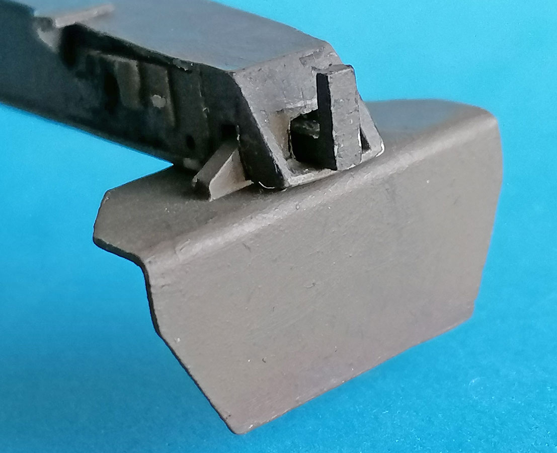
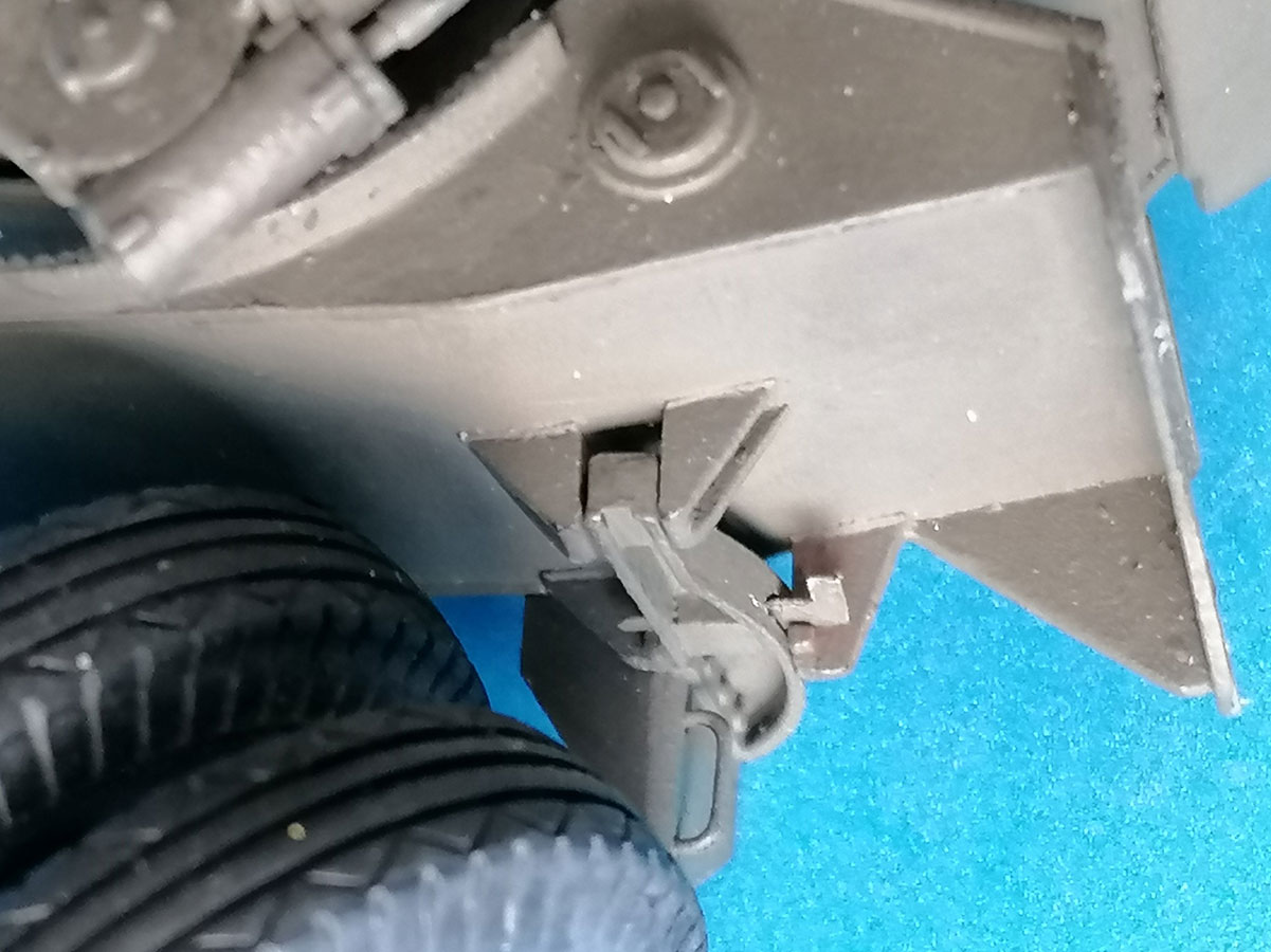
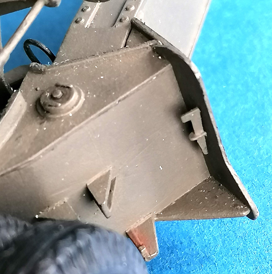
With the trails, the first thing is to exchange the "arrow" on the left one with a "Y" to receive the arrow on the right trail. I noted that in firing position, the rear spades A3 are secured to the trails by L-shaped keys that can be made from 1 x 1mm styrene strip; to insert these correctly, corresponding holes have to be cut into the ends of A11 and 12, just as they are present in A8 and 9. Doing this before gluing the trails together is easier than later. In traveling mode, those keys could be stowed on the outside of the left trail in the bracket somewhat forward of the octagon for the lifting screw wrench. That was the way with the short-barreled 203mm howitzer; with the long 155mm tube, the keys instead were used to secure the traveling lock below the breech.
On the prototype, the front trail spade supports (kit parts A34/35) have a narrow slot or "channel"cut into the ones going on the carriage outside, to arrest the spades with flat "keys". (These keys will else be stowed on the right trail outside or used to arrest the trail doors A23/38 in traveling mode.) The respective other spade supports have a steel bar welded to the side.
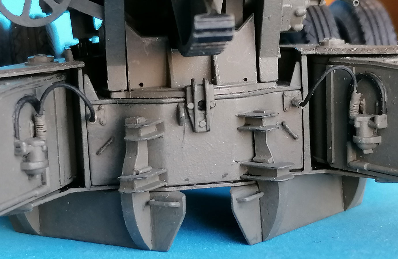 And here's how I think these contraptions work: The spades are placed below the carriage, above or in the holes dug for them, and pushed sideways towards the center until the supports are seated in the braces there, with the welded-on steel bars resting on top of the lower ones. This also moves the outer supports into place, where the keys are pushed through them, also resting on the lower braces. The effect being that the spades will be pulled from the ground when the carriage is lifted.
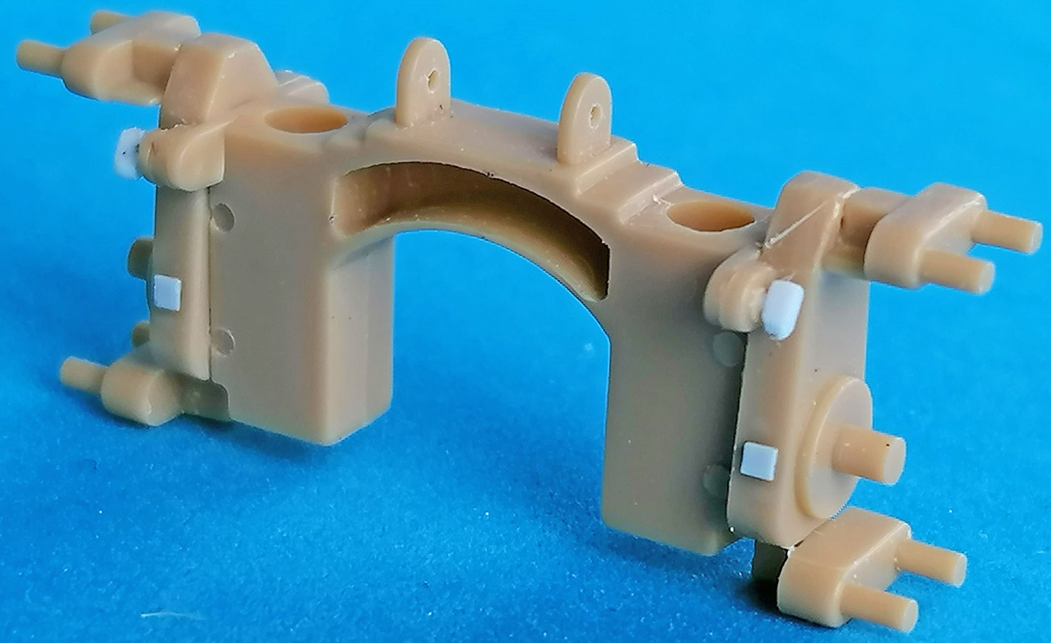
 A problem arose when I tried to mount the spades underneath the carriage: When the supports in the center were in place, the outer ones would not fit into their brackets on the carriage outside. This resulted from these brackets being molded at right angles to the rear part of the carriage body, whereas they are canted forward on the prototype. I shaved off these braces and made new ones from 0.5mm strips and triangles. To achieve the necessary space for the keys, the "channels" had to be heightened (on all four supports) by cementing on pieces of 0.75mm styrene before the slots could be drilled and cut out with a jigsaw blade. The keys were cut from 0.25mm sheet aluminum.
 The Eduard set 35 295 is discontinued – and rightly so, as only very few parts of it make sense: Replacing massive steel spade brackets with sheet metal is nonsense, the offered replacement hinges for the periscope case are supposed to be mounted in simply wrong places, the PE trail "doors" are misssing the triangles on their tops, and the list goes on. The only parts I eventually decided to use were the spade key stowage brackets on the trail outsides, the ramming/cleaning staff stowage brackets on the insides, and the hand brake ratchets. And then, when I was just shaking my head at the seemingly senseless placement suggestions for parts 19 and 38 and considering to disregard them, I found on p. 28 of TM 9-3038 that parts 19 are "Pointer Plates", showing whether debris lodged under the bearing surfaces of the lifting screws (B41) prevents correct raising of the carriage – provided you've added "Alinement Plates" on Bogie Cross Beam B42. Once you start looking for them, the pointer plates can easily be seen in TM and Toadman's pictures. And the function of 38 is to guide the brake lines coming out of the carriage "tunnel" sides, for which you have to drill holes there.
 |
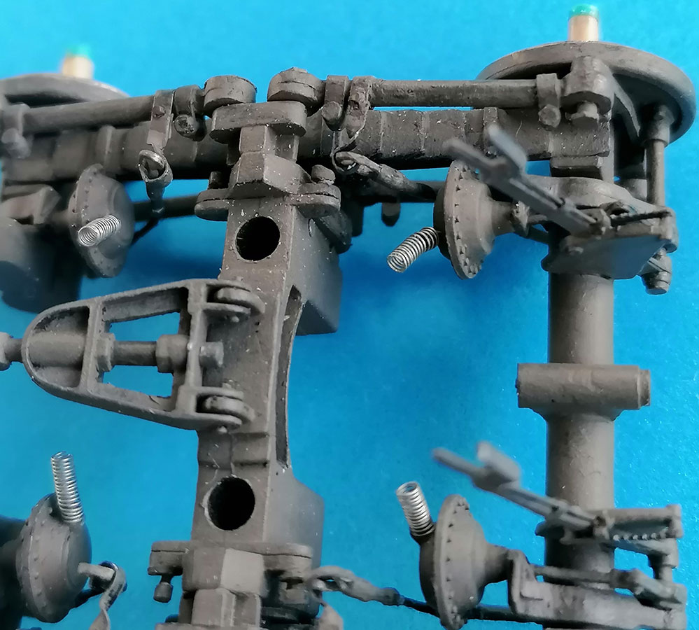 |
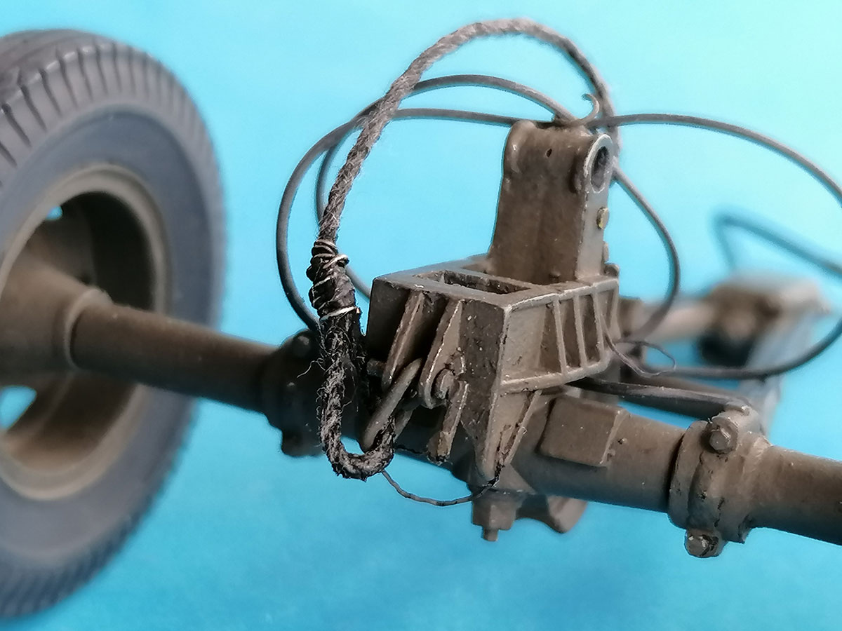
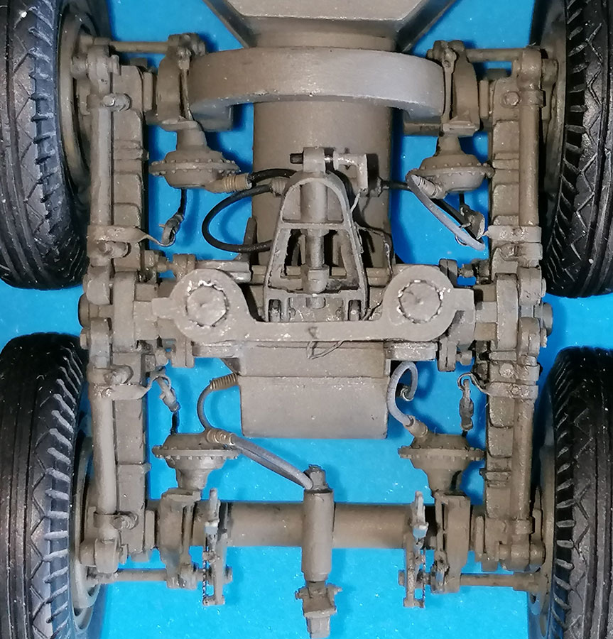
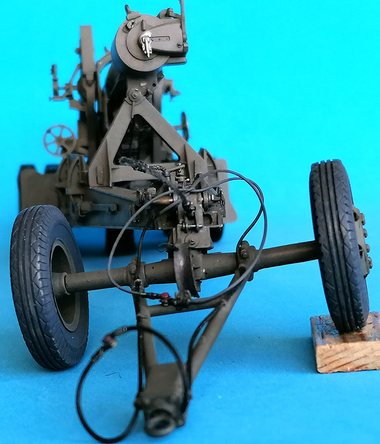
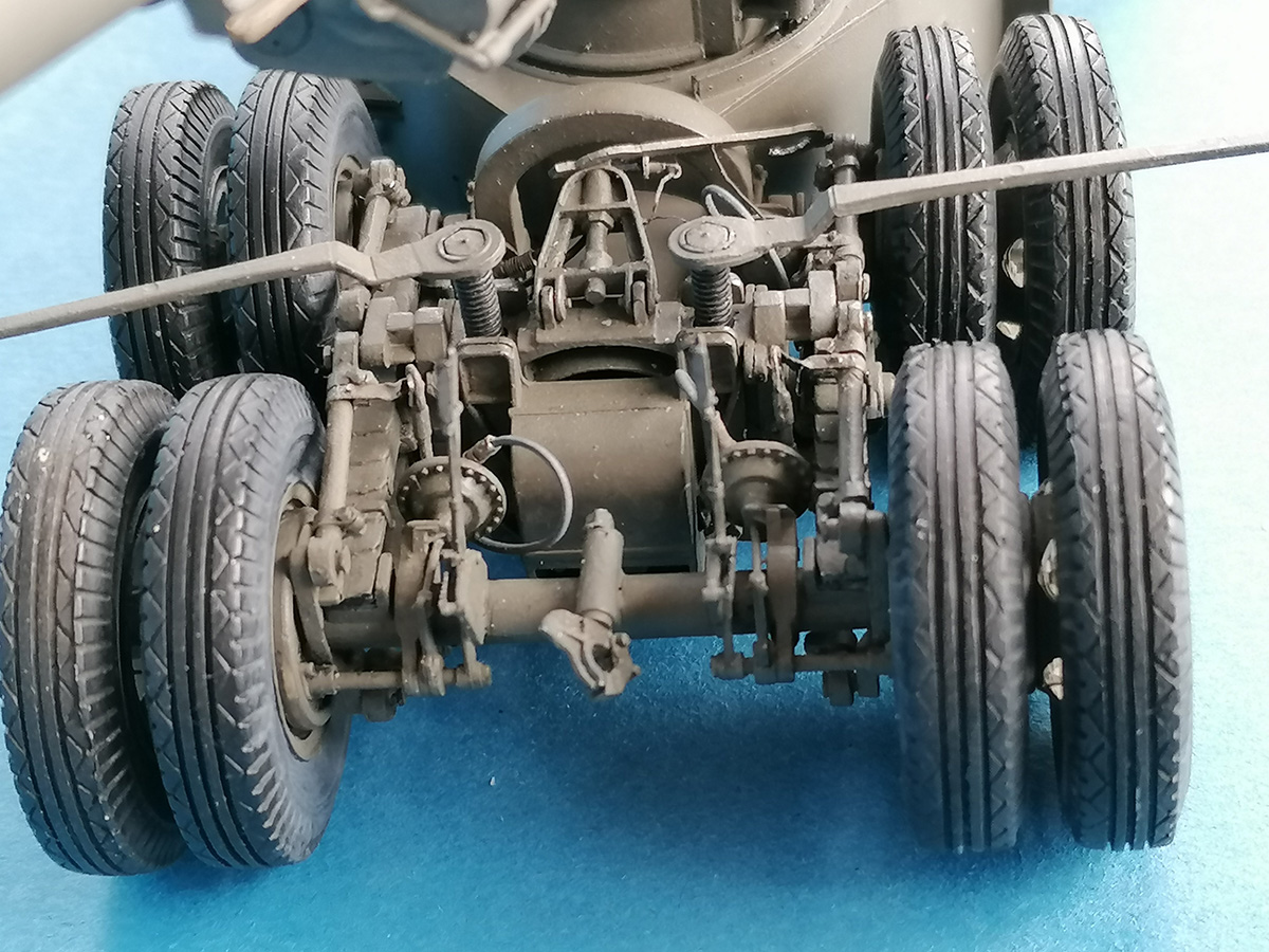
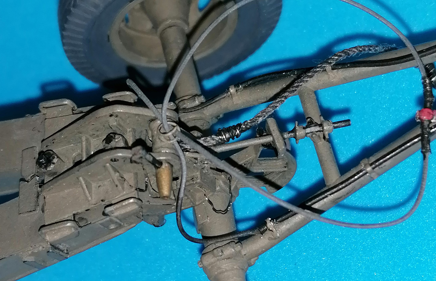
Assembling the wheeled parts offered no problems. On the brake diaphragms, however, I installed little spirals from thinnest wire wrapped around a drill bit to receive brake lines of black rubber filament. My carriage towing pintle was cut apart and drilled out to be reassembled with 0.5mm plastic rod and stretched sprue to be functional in case a styrene Mack NO truck would be released in 1/35 scale – a guy may dream, right? The hand brakes were detailed with PE ratchets and stretched sprue.
I didn't glue the torque rods, they're held in place by 0.3 x 1.4mm hex-slices to keep them movable. The little clamps around their ends were composed of 1.2 x 0.3mm round slices between the ends of 7 x 0.25 x 1mm styrene strips plus 0.25 x 1mm hex-tops.
 |
 |
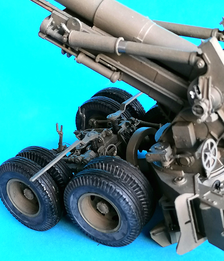
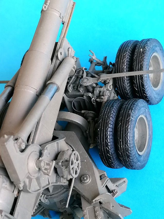
The lifting screws will move the wheeled contraption, thus lowering the carriage to the ground for firing or raising it up for transport.
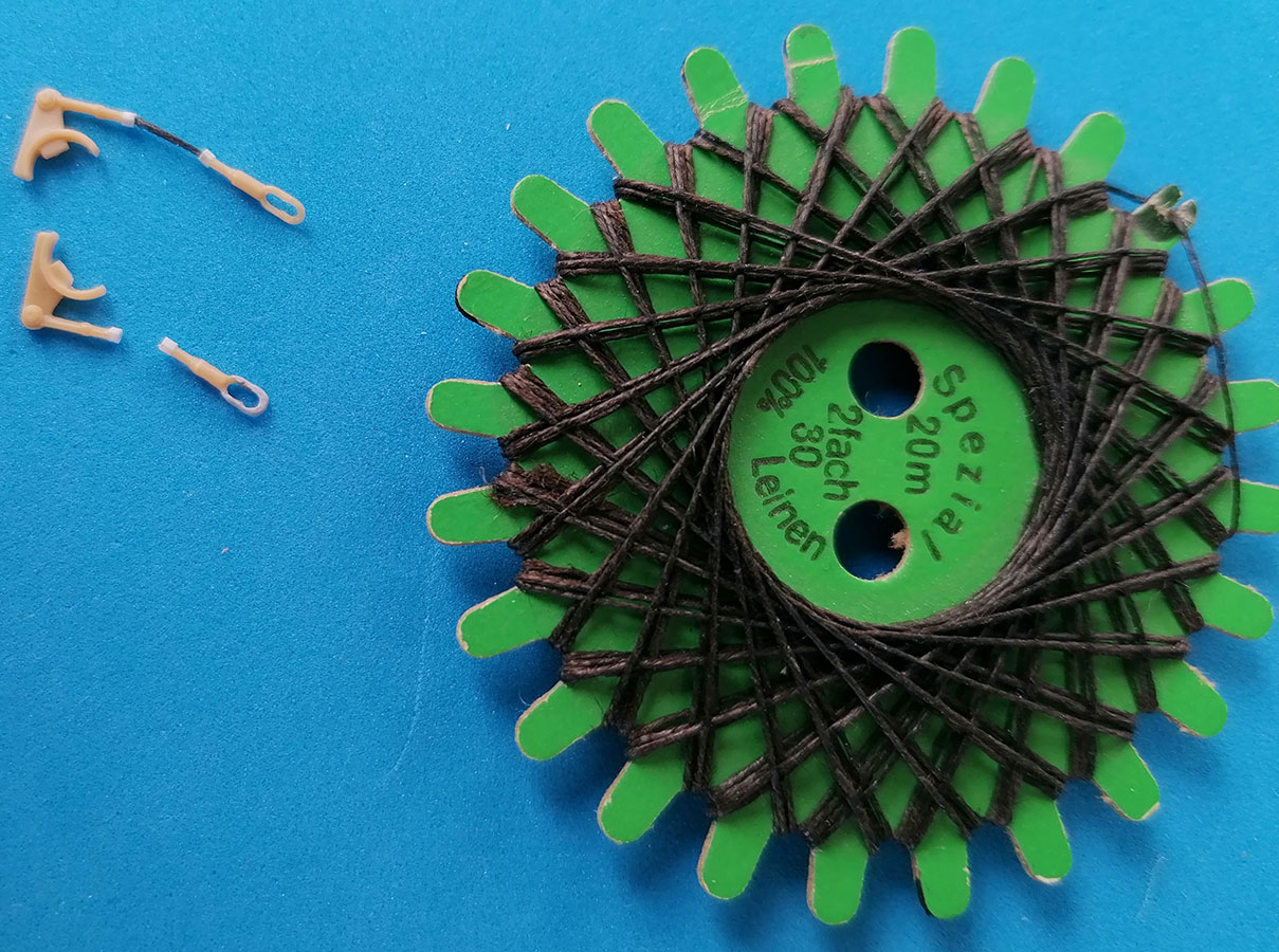
Unfortunately, the instructions don't mention this, let alone tell you how far up this "vehicle" has to be lifted for the firing position. The function of parts B34/35 isn't evident in the instructions – and the way they're given in the kit, they're only correct for a gun in firing position: After lowering the carriage, further turning the lifting screws will lift the wheels off the ground, leaving them suspended from their springs' axles. Which would make them swing at every shot. To avert this, the center part of B34/35 on the prototype is a piece of wire cable, and their eyes hooked to the raised Bogie Crossbeam (B42) would stabilize the running gear. In travel mode, however, the eyes of these cables would be stowed on sheet metal hooks on the torque rods. – Drilling out the kit parts' eyes and replacing their centers with 5mm of strong linen thread between two slices of hex rod made them workable with new "hangers" on B42. The hooks on the torque rods were bent from 14 x 1mm sheet aluminum strips. .
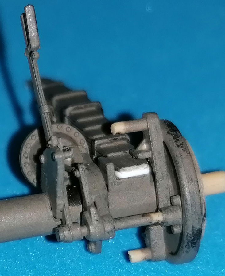 And when I tried to put it all together, the leaf springs' ends sat very loosely on the brake drums. Photos showed that the small protrusions on the drums limit the springs' play, because there are two leaves, not just one as the kit offers. Little pieces of 0.5mm styrene strip corrected that.
I avoided using glue here wherever possible, especially at the springs' axles, to keep maximum mobility for the assembly.
 At the front of carriage sides A6 and 7, four drain (?) holes were drilled in.The bottom of carriage base A30 as well as top plate A31 should protrude beyond these side walls, but, as top and bottom are given virtually flush with the sides in the kit, the corresponding cutouts in braces A19 largely had to be filled. Photos of the prototype show that the braces are welded around the trail openings and that the weld beads extend on the openings' top. To copy this, styrene strips of 0.38 x 0.5mm were cemented around and the resulting angle filled with stretched sprue that was softened with liquid cement and structured with a knife blade. Sanding all this into a satisfactory fit took some time. And then it turned out that the locking "U" on the doors was too short to allow a key to pass through it on the other side of the braces. Eduard's brass replacement doors, for their part, were too thin and lacked the triangle on their tops, so I eventually had to sand down the kit's braces to 0.5mm thickness. The thin spade locking keys double here to keep the doors closed during travel.
 As I always want to show my models in different states of operation, these doors needed working hinges. Evergreen 2.5mm tube was treated as for stretching sprue, with a very fine wire inside; thus, pieces of 0.5 mm diameter tube could be cemented to the dooors' and trails' molded-on hinge plate representations after shaving off the "hinge pins" and the front half of the plates on the trails; hinge pins from the stretching wire completed this madness.
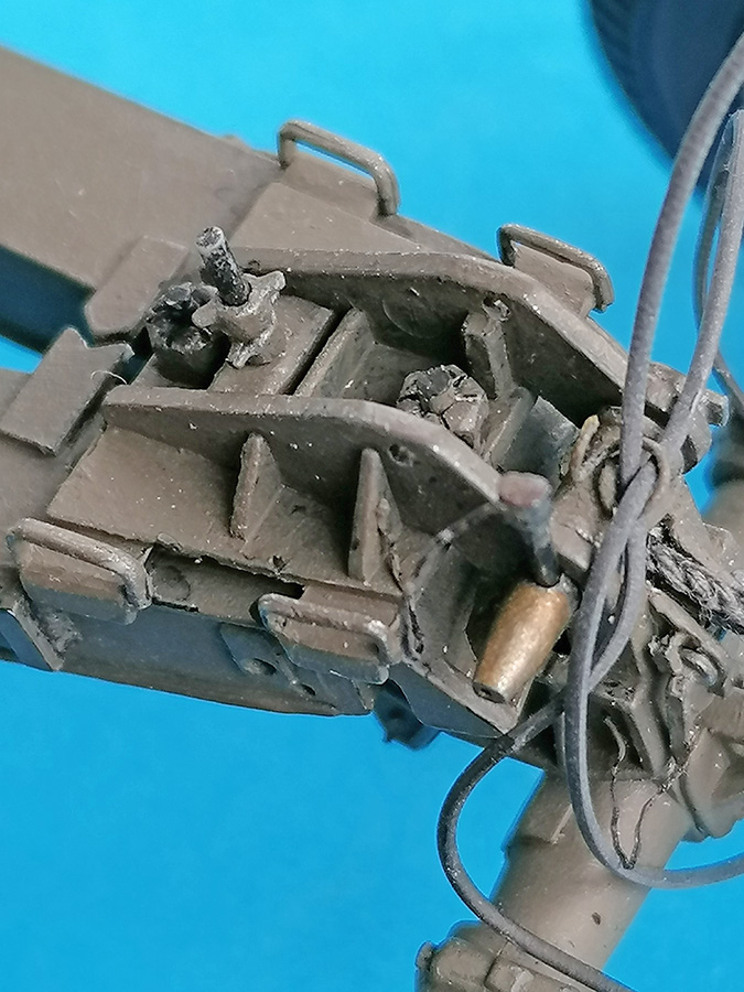
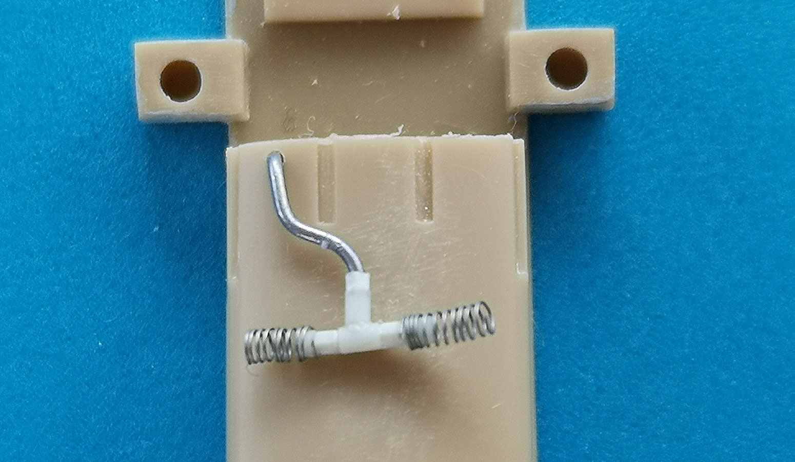 On the trail insides, I cut off the "trapezes" over the air brake couplings which I added from Perfect Scale resin, and re-installed the trapezoid protectors over them. Eduard PE boxes with a set of staffs made from 1mm Evergreen rod replaced the molded-on cleaning staff storage points. The bogie lifting screw wrenches had their stowage bracket imitations sanded off and replaced by contraptions bent from PE runners. Short pieces of stretched sprue were added to the air filters to mount flexible air lines; a "T" from the same material was mounted on the "tunnel" between the gun and the wheels, together with a piece of wire leading into that tunnel and the air reservoir. All flexible lines were made from rubber filament.
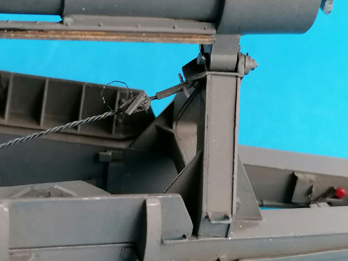
 The Travel "A" Brace (A20/21 plus handles A27 that aren't mentioned in the instructions) needs some work, too: The protruding part of the "half pipe" is bent downwards to guide the breech sliding up, and it has two triangles underneath to hold the upper end of the brace securing cable. The part was cut off and 0.5mm sheet cemented on that was then sanded down to give the intended angle. The triangles are from thin sheet.
 |
 |
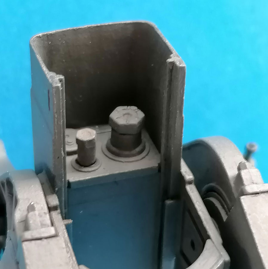
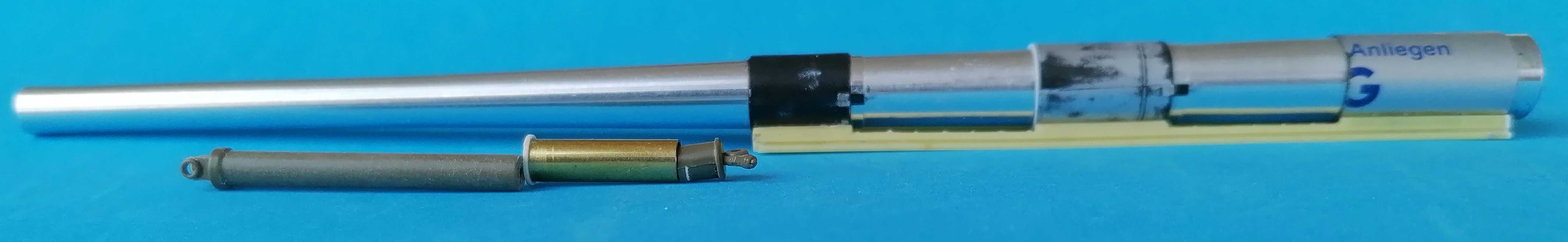
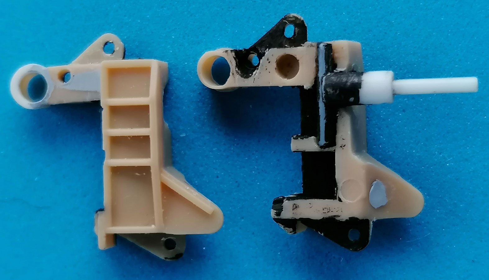
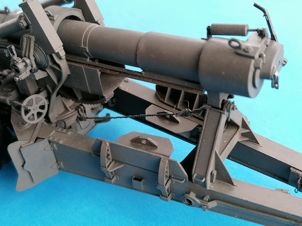
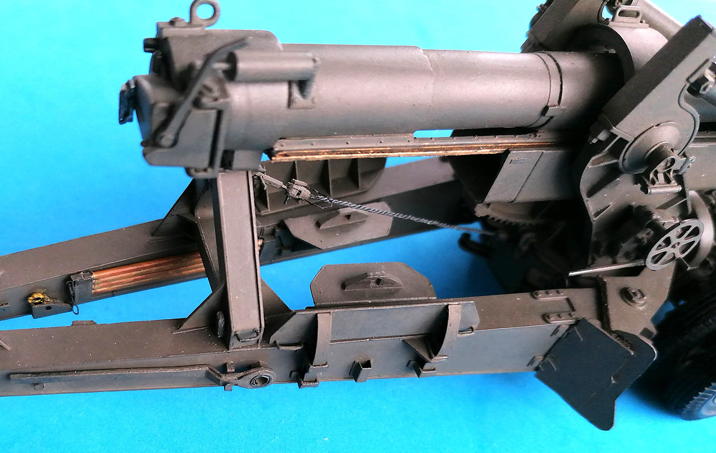
For an operable tube locking mechanism, I replaced the brace's locking lever and the "plate" it is mounted to and drilled out their axle so a disk of suitable diameter could be glued eccentrically to a new axle which received the replacements, plus a hexhead nut at its other end. Removal of the recoil piston nuts on the breech should only be done after drilling through their centers; that way, the holes in the lower part of the breech will be in the correct places. That is important for the installation of the eccentric's axle in the larger hole so the breech will be arrested after a partial turn. The recoil piston nuts were glued to styrene rod of suitable diameter that fit into the holes in the cradle and now stop the tube from going forward all the way.
The end parts for the Travel Lock Cable were cut and sanded from 2mm and 0.5mm styrene rod, 1mm hex rod, and 0.5mm sheet. The cable itself was twisted together from three strands of 0.3mm brass wire, but I still hope to find a real wire cable of the correct diameter.
Gun
For the gun, I had the parts of a Tamiya M40 kit minus the gun tube and the parts for the slide rails and the bands that connect them to the tube, as I had used these to correct my AFV Club M40 model. However, I had made resin copies and bought a Tamiya metal barrel. The cast-offs for the fastening bands turned out to not have come out straight, but were easily replaced with pieces of cheap plastic ball pens of suitable diameters. The breech can be changed into one of correct diameter, as described in my AFV Club M40 build report (https://panzer-modell.de/berichte/m40/m40e.php). This can be advantageous, as the Tamiya breech has a slightly different angle for its appendix so it won't fit into the travel brace's "trough" and you'd have to graft this area off the AFV part. At the front of the Tamiya breech, I installed an angle of unknown function – 4mm wide, glued together from 0.25mm strip: 1.5mm vertical and 2mm horizontally in front of that, plus two 0.8mm hexheads in the corners of the vertical shank.
And there's another missing detail in the M59 kit: the "Front Retracting Bracket" at the rear of the front tube fastening band, needed to pull the barrel back into traveling position. I bent this from 1mm copper wire and hammered its end flat so it could receive two small nuts. Builders of AFV Club's M1 kit will find this as part E3 and should ignore their instructions' order to mount it on the center band. In either case, DO NOT stick this thing on the tube before you have inserted that into the cradle – it will not pass under part C33, the "roof" between the cradle sides.
 As opposed to my Tamiya M40 build (https://panzer-modell.de/berichte/m40_tam/m40e.php), here I did not super detail the breech, as I had decided early on to show this gun in the process of being readied for towing, but have only added the "catch" to the breechblock operating lever. The kit equilibrators C12,18 have a too little difference in diameter: the lower parts would have to be drilled out and the pistons of the upper ones replaced with thicker ones, so I used the Tamiya equilibrators. There, though, I found it necessary to sand off the rings around their pistons and to cement 0.25 x 0.5mm styrene strips around the upper ends of the brass tubes instead. The slide rails underneath the tube were later painted with a mixture of gold and matt black to represent bronze.
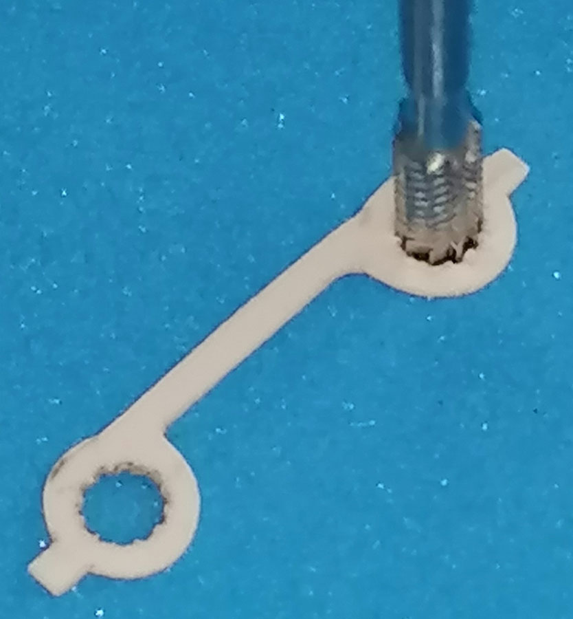 Installing the Tamiya trunnion supports on the AFV Club carriage was a little more difficult than expected, as the Tamiya parts are almost 1mm wider than their surround in the AFV Club top of the carriage. Widening that half-circle solved this problem. Interestingly, however, the AFV Club parts C10,11 are some 2mm higher at the front than the Tamiya ones, and so is the position of the cradle – and on my model, that results in the front cradle lock B33 being too high; so it just hasn't been installed yet... The "lock bolt" on its top had to be drilled out and replaced by a separate one anyway. – The most demanding scratchbuilt item was the Lifting Screw Lock, a strip of sheet metal with two multi-toothed holes at its ends like those in the Lifting Screw Wrenches – I achieved that, although not perfectly, by hammering a 3mm router through 0.4mm plastic sheet.
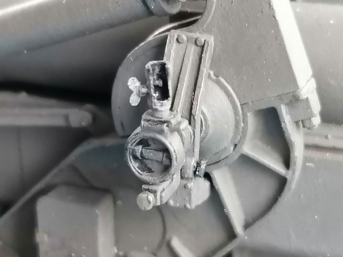 The rendition of panoramic telescope M12 isn't the best in either kit, so I removed the AFV one from its mount by cutting off the part above the "ridge" and drilling out the lower part after removing the eyepiece. Cutting out a slot where the eyepiece would pass and adding an arrester rod inside with a wing nut outside made it ready for being cut off its mount and re-glued at a slight turn.
The trunnion support upper parts (AFV C31,32) received hexhead nuts in their lower front ends.
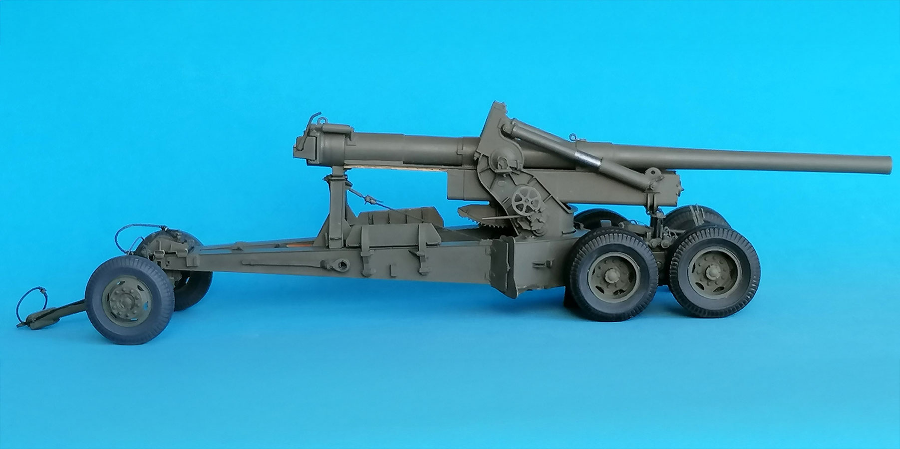
Limber
Intensive study of the kit and the TM showed that AFV Club has designed the kit parts for a gun in firing position and not really wasted thoughts on the limber's details: It is obvious that the drawbar should be able to move up and down independently of the gun trails and that the limber axle should be allowed to cant (think potholes), whereas the kit parts only allow the limber to steer. Apart from that, the instructions don't even mention that the carriage should be in raised or lowered positions, let alone how that should be achieved and look with the model. And there are more things to correct and add once you know how the whole thing is going to work:
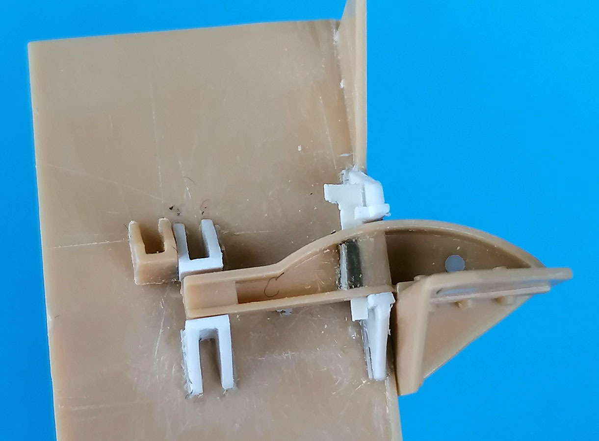
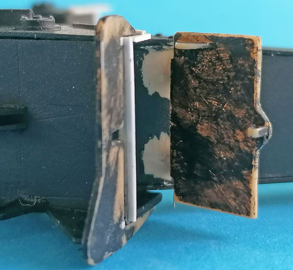
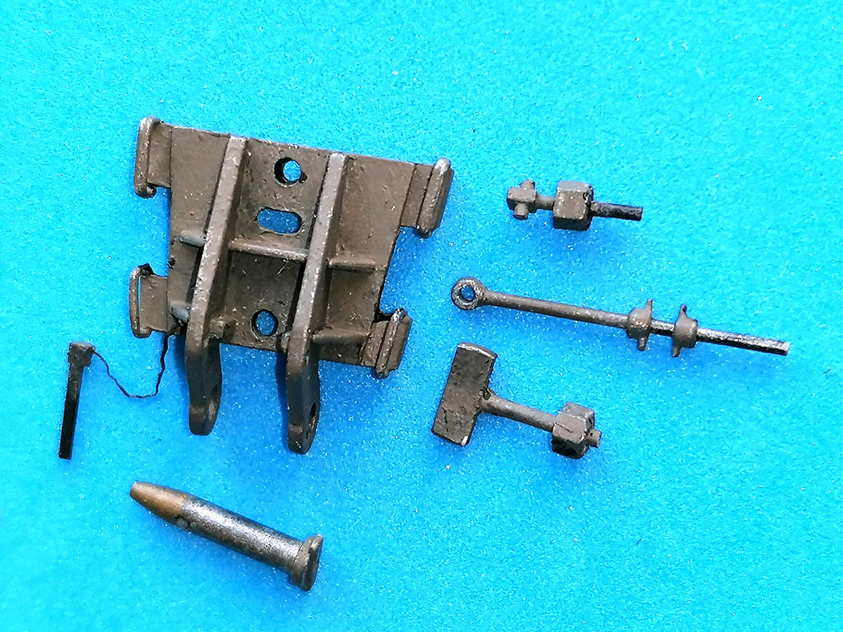
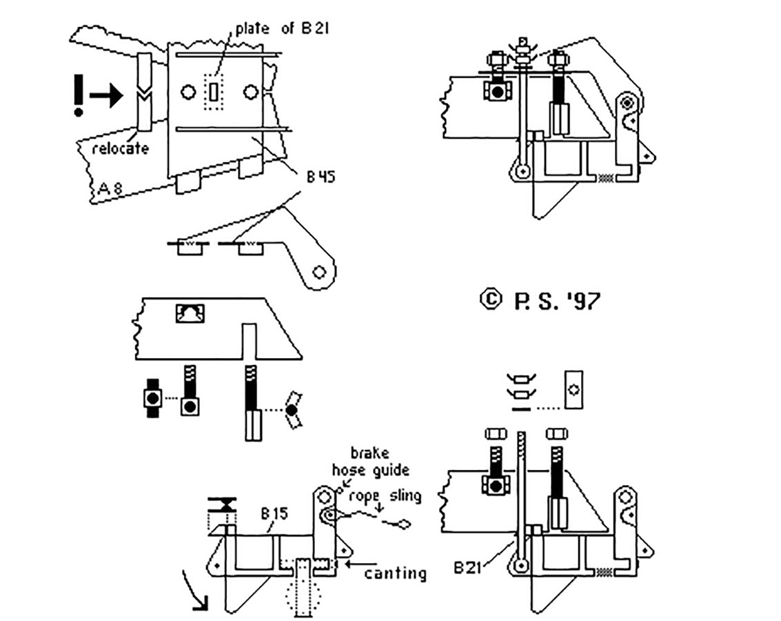 With the gun carriage lifted off the ground and the spades stowed, the trails are folded inwards. The Lifting Clamp's coupling pin is pulled out and the clamp placed separately on the trails, to be fastened to them by two bolts with lateral protrusions that go into the trail spade cutouts and the supports on the insides of the trails, respectively. Their threaded ends pass through the clamp to be held in place by large nuts (also when the limber is separated from the gun). The limber is brought to the trail ends and the lifting bracket's coupling pin hole lined up with those of the clamp. Once the coupling pin is inserted and secured, the eyebolt (kit part B21) is removed so the draw bar can be folded down and hitched to the towing vehicle; the lifting sling is hooked to the towing vehicle's winch.
By slowly winching in, the lifting bracket pulls up the clamp plus trails into the traveling position. To avoid a rollback, the eyebolt's eye is inserted through the slit in the clamp and fixed at the rear of the lifting bracket; the wing nuts are fastened on top of its "plate" covering the slit. According to the TM, the end of the lifting sling is to go to a hook on a trail that the illustration marks as not visible...
I started work drilling with a 1mm bit through the nut below the axle that holds the pin on which the clamping assembly rotates, up through the axle and then cutting off said nut (and saving it). The kit-supplied pin and the corresponding upper half of the hole in the axle body had a diameter of 2mm, so I drilled a 1mm hole into a piece of 2mm rod and cemented a length of 1mm rod into it.
 The two halves of Limber Lift Bracket B14/15 had the pins on front and rear protruding brackets drilled out. The lateral rims of the hole on B14/15's tops were increased to the diameter of the holes in clamp braces B23/24.
These had their representations of the "Trail Coupling Hitch Pin" ends shaved off and saved.
WARNING: Clamp B45 forces the trails a lot too close together – if you want to build your gun in a realistic traveling position, you'll either have to cheat a lot (like I did) or widen it for more than one millimetre right away. (Remarkably, the corresponding part of Revell's 1:40 Long Tom of 1958 vintage is wider than this 1:35 part!)
 The two "warts" underneath the clamp should not be cut off, as the instructions tell for the "Transport Position", but drilled through from the top. (However, they will have to be laterally trimmed if the trails are to be shown closed.) The cylindrical protrusion on top of the clamp must be removed and a "slot" of 1 x 2mm with rounded ends cut instead that will let the eyebolt's eye pass and will then be covered by the rectangular plate that's molded to the bolt. I cut off that plate and cemented it onto 0.5mm styrene; the thickened result was drilled through for a new bolt, as the kit one had mold shift and the plate should be positionable for firing or traveling mode, which also goes for the eye bolt's wing nuts.
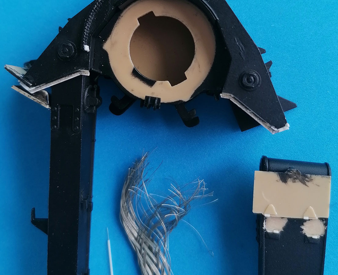
 Before the limber bracket's halves could be glued together, a hollow for the Lifting Sling had to be dug above the front bracket parts that are to hold the eyebolt: I drilled a shallow 0.5mm hole into both halves and then opened them towards the front. Another small hole drilled across would allow a fixing bolt to hold the lifting sling's eye. The eyebolt securing pins at front and rear of the lifting bracket were constructed from narrow styrene strip plus tiny sheet circles with one cut-off side, cemented to 0.75mm rod so when they're rotated they can be arrested by tiny "angles".
B14/15 were now clamped together to allow drilling a 1mm hole at their bottom from front to rear, right into the center brace, but not quite through it. A rod of suitable length was cut and inserted, to allow a dry fit of axle and lift bracket whose 2mm rotation axle had a notch filed into its end to glue it "around" that horizontal rod. At the bracket's front, the hole was covered with a styrene disk and tiny nut. The bottom opening in the bracket was carved out laterally to allow for canting of the axle. After the glue had set, the "nose" at the top rear of the bracket was not cut off, as AFV would have it, but carved out vertically at front and rear to allow the eye bolt to pass (which would only be visible with the limber separated from the gun).
I scratchbuilt one of the clamp securing bolts from 1mm rod and a cube of 1mm square strip with a 0.5mm cross rod, the other one from a 0.9 x 3 x 4mm rectangle with a bend in the middle, plus 1mm rod. The nuts came from my spares and hold by friction. My clamp is joined to the lifting bracket by a new coupling pin made from 2mm rod with one conical end plus the "T"-shaped end sliced off clamp brace B23. The conus (made of bronze on the prototype, and detachable) begins where the pin exits B24; right there, there's a hole going through the pin into which a key of semicircular cross shape goes.
And here come the problems with AFV Club not having constructed the kit for a gun on the move: The too tight clamp holds the trails too close together to let the bolts pass – that can be remedied by some sanding and drilling. The eyebolt's eye, however, would need the removal of substantial (and thus obvious) parts of the trail details below the clamp, so it has to be inserted from the bottom on my model. Now it also became clear why the instructions would have the "nose" at the bracket top's rear cut off – it, too, doesn't fit between the trails, hollowed out or not. Off it went, and now at last the trails could be hooked up to my M5 limber just as on the prototype.
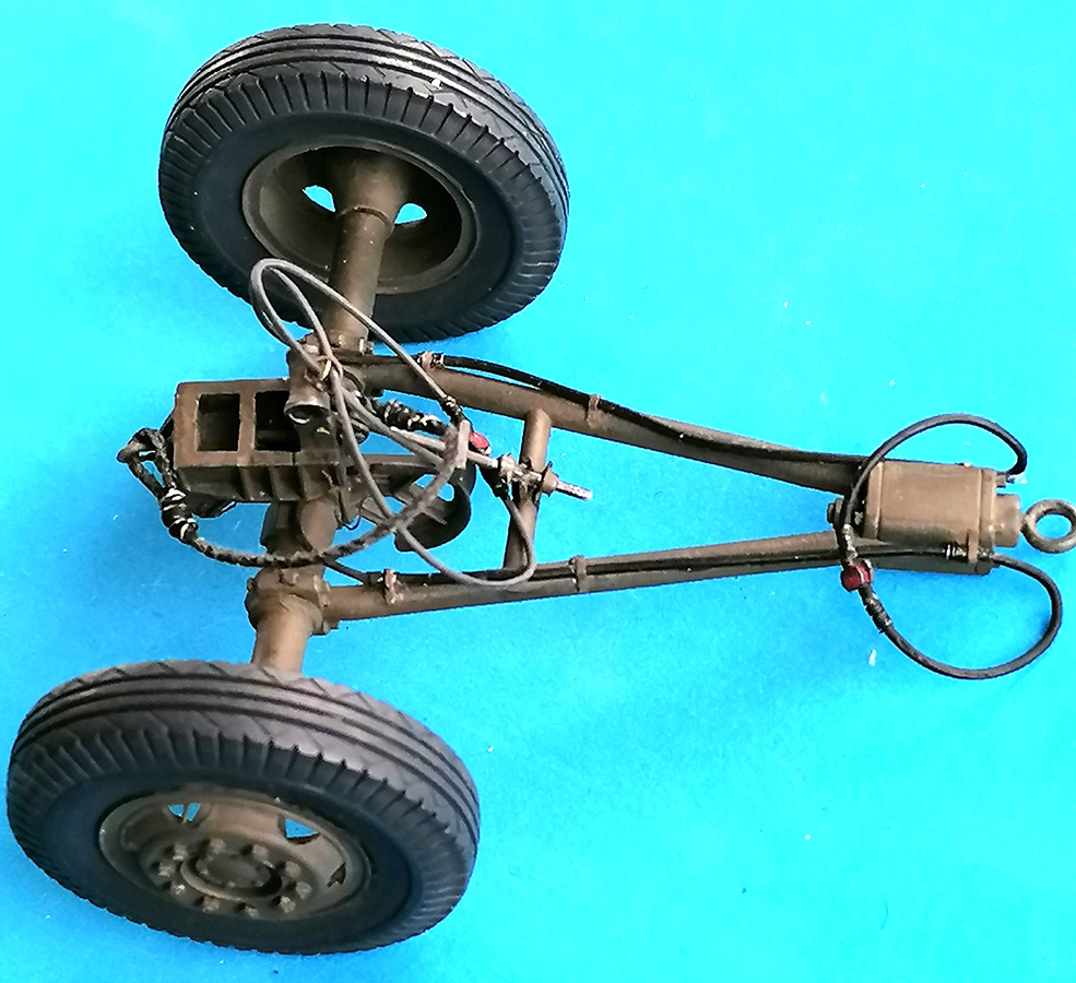
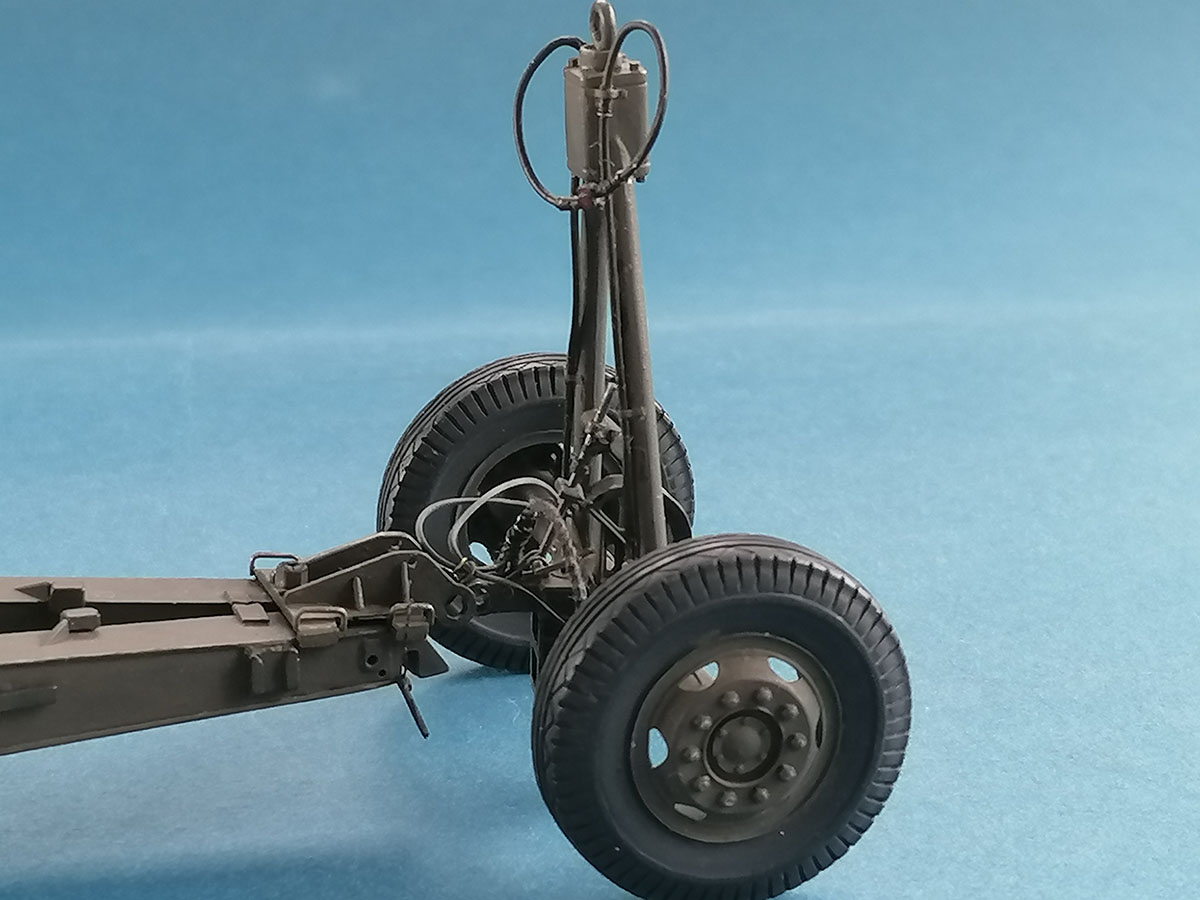
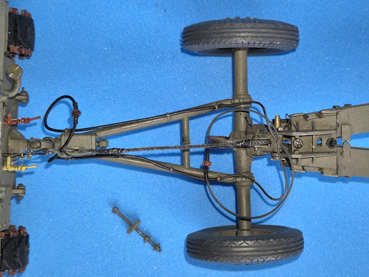
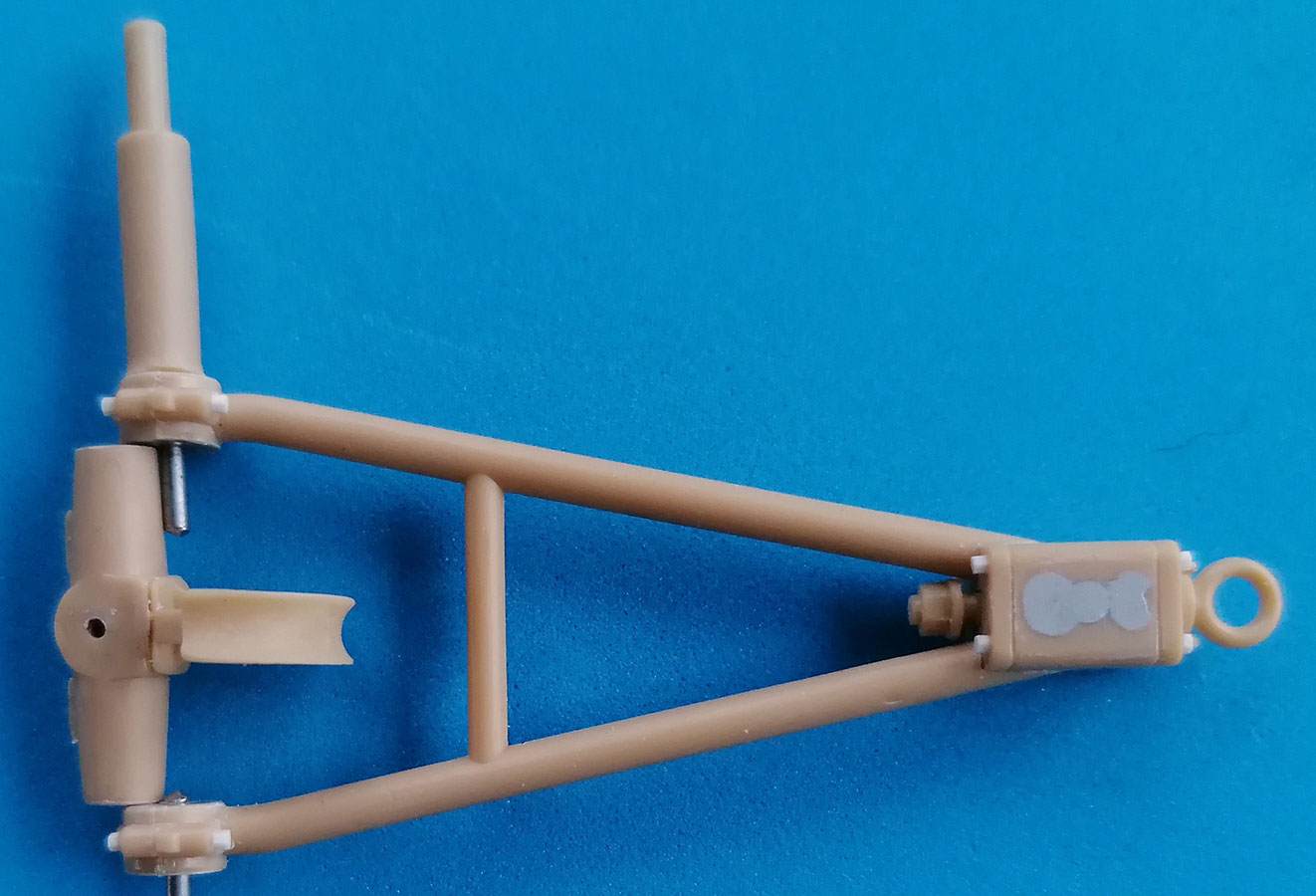 Back to the drawbar. Using the kit's five-hole wheel rims, making it movable is rather easy: Cut through the axle on the outside of the drawbar "clamps", drill through them and into the central part of the axle, then also cut on the other side of the clamps. Insert wire "axle pins" and re-cement the outer axle parts before you mount the kit wheels. With the Masters Productions wheels this was a lot more complicated, but feasible, too.
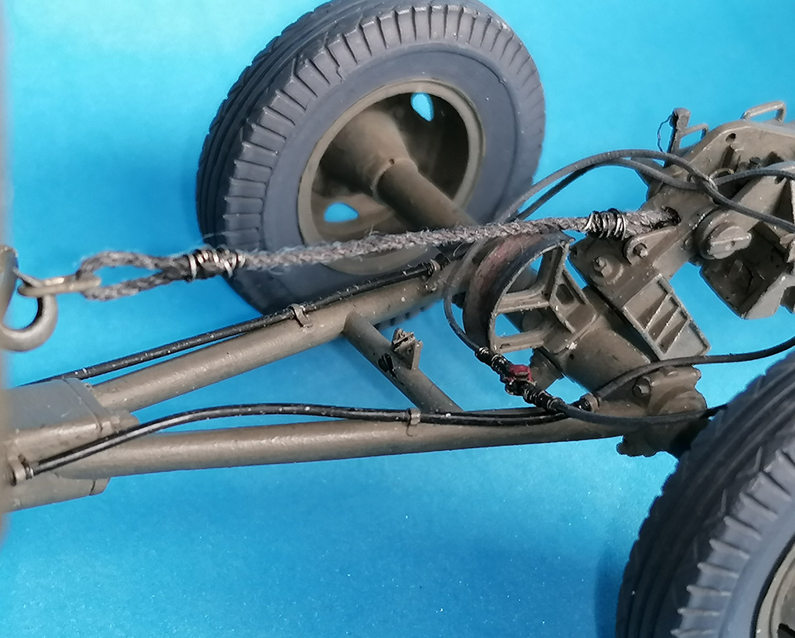
The clamps proper received light razor blade cuts at top and bottom to show that they represent two parts that are held together around the axle with hexhead bolts, made by slices of hex rod. Tiny holes were drilled opposite the draw bar to represent clamp grease points. Lifting Sling Guide B22 was glued to the axle's center part after having been hollowed out with a rat tail file and receiving cutouts to hold the plate of the eyebolt. The lifting sling itself (nylon string) received a wire chain link and was installed in the lifting bracket with a piece of 0.75mm rod. A short piece of half pipe was glued to the eyebolt support in the draw bar center; on the stowed bolt, the wing nuts go before and behind that support.
The air brake hoses were made from rubber filament. The couplings are punched out styrene slices with tiny "locking ridges". The wire reinforcements are just that – finest wire coiled around a drill bit and then slipped on the lines. Installation on the drawbar was by narrow strips of thin styrene, guidance over the lifting bracket through a piece of thicker wire "spiral" glued to its top.
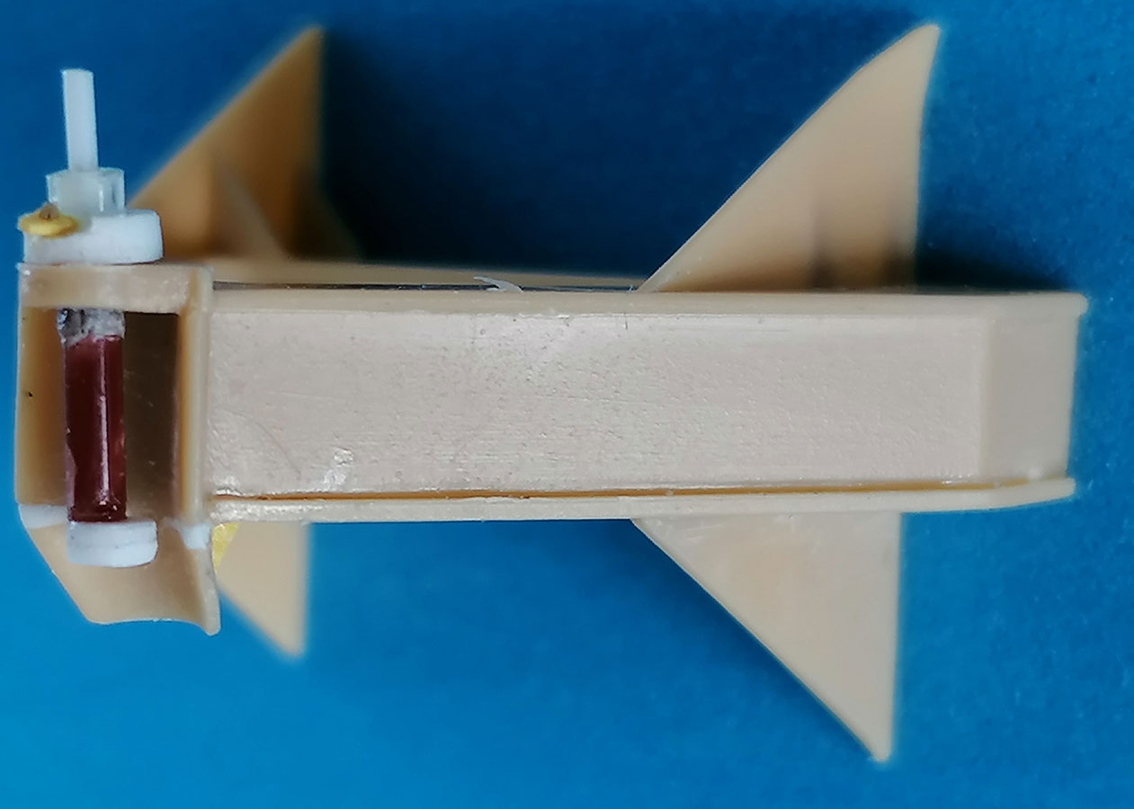
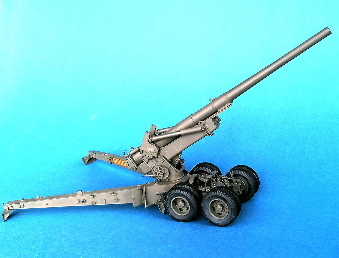
And the final disappointment was that the kit's lifting screws are not designed to hold the carriage in the transport position: The Bogie Crossbeam will have to be cemented in to show this version, or you have to place a suitable piece of black foam rubber underneath, as I did for taking the pictures.
| Painting / Weathering ... |
... is what I hate about model building. So, when at long last it couldn't be avoided any longer, a first layer of Citadel "Chaos Black" from the rattle can was applied and then covered with Revell Aqua 46 NATO Olive. A few dabs of gun metal, silver, dark gray, and black finished the model.
| Conclusion |
A kit that wasn't good even when it first came out, because lacking research had led to many important parts given in wrong shapes or missing altogether. It needs lots of correcting work, but its offering the M5 limber makes it indispensable, given the wide range of international M59 users.
Bewertung:
| Price / Value: | ***** | Fitting: | ***** |
| Detailing: | ***** | Skill Level: | ***** |
 |
 |
 |
 |
 |
 |
 |
 |
 |
 |
 |
 |
 |
 |
 |
 |
 |
 |
References:
© 06/2025 Peter Schweisthal
1791 readers of this report since 15.06.2025