|
|
 |
| The Original |
In 1944, the US Army decided to mount the proven 155 mm cannon "Long Tom" and its 203 mm howitzer "sister" on Sherman HVSS hulls. Test vehicles T 38 and T 89 took part in the shelling of Cologne in early 1945, production was taken up after the war's end. The SPGs, dubbed M 40 and M 43, were primarily used in the Korean War; examples sold to allies remained in service much longer: with British reserve units, for example, until the 1960s.
| The kit |
After having corrected the AFV Club 1/35 kit of this vehicle with the help of a Tamiya gun tube and much work (http://www.panzer-modell.de/berichte/m40/m40e.php), I wanted to build Tamiya's version for comparison. Accidentally, I could pick up an irreparably damaged Tamiya model to cannibalize.
A first assessment of the kit and its instructions showed that Tamiya isn't infallible, either. On the box side, the red taillight is depicted on the right, and while there's a leaflet with color photos of a museum M40, the instructions contain no sprue plan to help find the parts, nor do they tell you where to place what markings on the model. As for the parts themselves, the external engine compartment fire extinguisher releases on the glacis are missing, as are the braces beneath the PE louvers in the same area. And for someone who had spent too much time studying references (see list at the end of this article), there were many more small details that AMS demanded to be corrected or added.

| Build |
Note: If painting and weathering is the part of modeling you enjoy best, you might consider to stop reading right here, as this is a BUILD report, by someone for whom anything after the completed construction of a model is the tedious part of the hobby, so you probably won't find anything worth reading about your favorite subject.
Hull
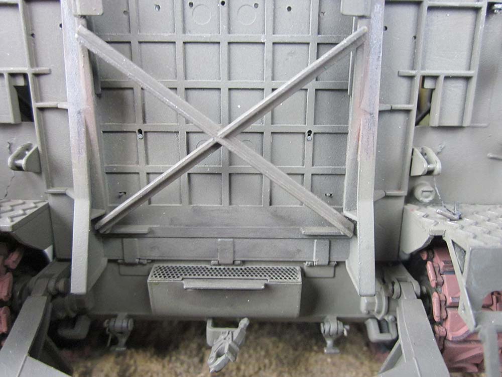
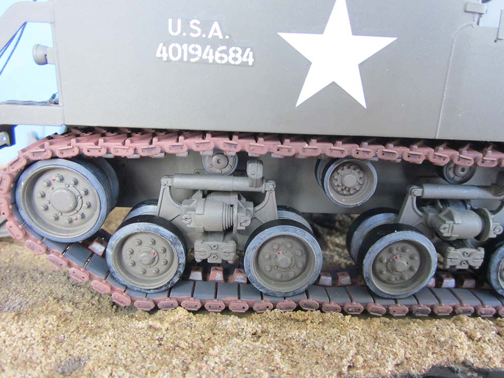
Following the instructions, I started with the multi-part hull. No problems here, except that the recoil spade is designed movable whereas the tailgate/loading platform is to be cemented in place, up or down. No way for me! Before cementing in the hull bottom rear wall, the respective outer hinges on it and the platform were shortened and then drilled through with a 0.3 mm drill bit before PE 'rings on sticks' from the model railroad range were cemented on as reinforcements. The kit PE arrester eyes on upper rear wall and platform were later replaced with ones from scale thickness styrene strips, and the arrester studs D1 were secured with flexible latex 'chains' from the upper part of black 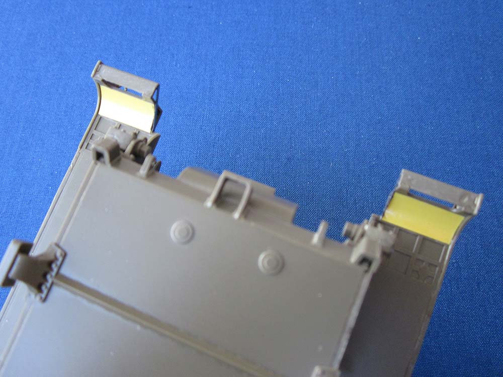 panty hose. The trailer light receptacle was detailed with a stretched sprue 'hinge' and a tiny piece of sheet for a 'lid handle'. Another little detail here were the missing rounded mudguards above the idler wheels, which were easily added from thin 15 x 7.5 mm sheet.
Being the unsystematic builder I am, I now deviated from the instructions and started detailing the mobilized platform: The holes for installing 'support chains' were filled, as these chains were by no way standard, let alone necessary to hold the platform, so my vehicle 'Courageous Confederate', one of the kit's marking options, was to be without them (as the Doyle book shows). The mysterious holes forming a crescent, however, were drilled through; I have a notion that they were supposed to support a long loading rail in different traverse positions of the gun. Four 'keyholes' and two more holes were drilled in, allowing the installation of two additional crew seats that I took from the scrapped kit. On the underside of the platform, two braces were installed that keep the support of the platform extension in its stowed position. And while I was in the area, I also mobilized this support by replacing its 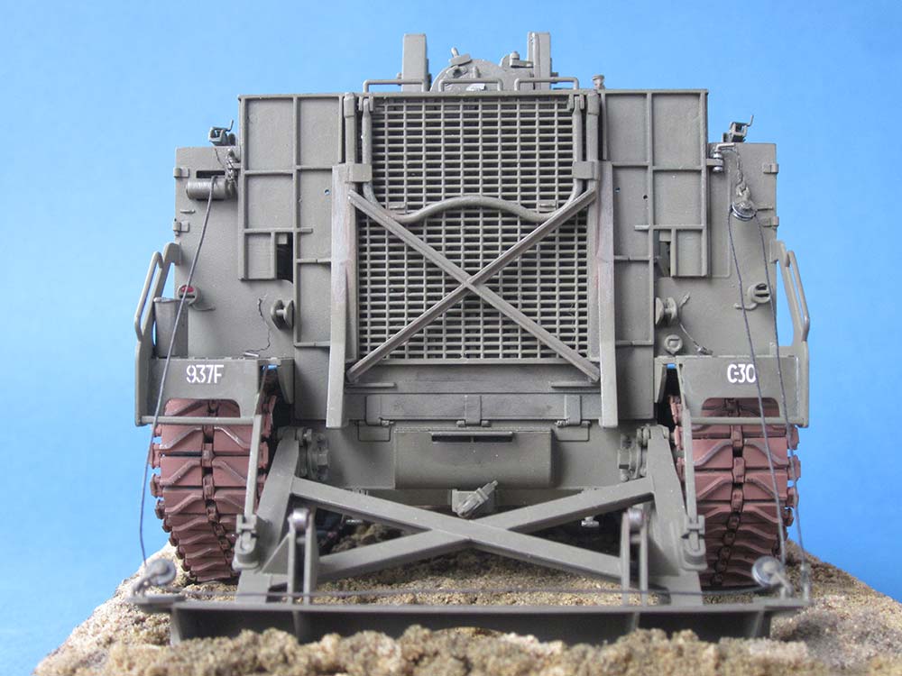 molded-on hinges with perforated little squares of styrene strip and hinge pins from stretched sprue. Two tiedown eyes were cemented to small styrene rectangles placed on the underside in line with the eyes on the rear wall.
The spade, too, needed a few additional details: After filling the prominent ejector pin holes on its 'corners' that support the lifting rope sheaves (D58/59), small diagonal braces were added here. The arresting hook supports (D67/73) needed small styrene strips added on top to keep the hooks from folding too far back, and the hooks are kept from jumping loose on the march by arresting studs that go into the holes on parts D66/72. The spade lifting rope sheaves on the prototype had protective covers, so, after cutting their grooves real deep to make them 'operable', such covers were added from the thinnest available sheet. The way Tamiya wants these sheaves mounted to overly long eyelets D33 in oversized positioning aids admittedly is foolproof, but doesn't look realistic, so I removed the aids and shortened the eyelets.
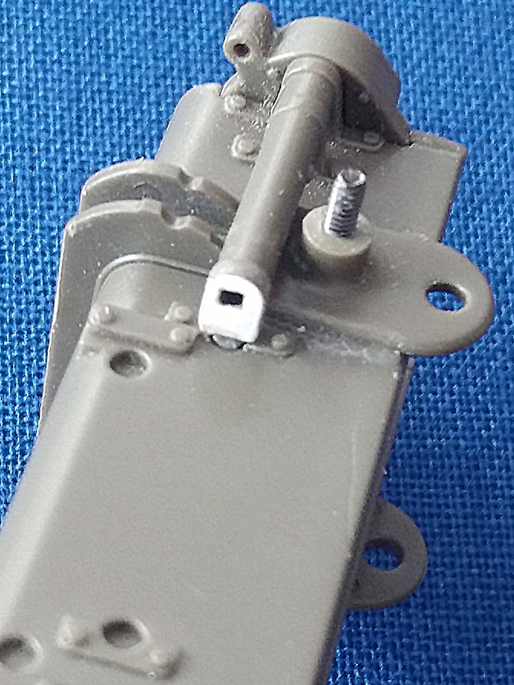
My winch rope is strong black sewing thread (waxed, from the shoe repair man), as that is more to scale than the kit supplied nylon string. Which led to an excursion to the winch, resulting in an added 'band brake' plus brake lever. And then I happened to look at my AFV Club model – to discover that the crank axle was located in the upper hole of the winch housing, not in the lower one, which photos in the TM (pp. 35,36) and at primeportal supported. (I know that the M40 at Ft. Sill, shown in the color leaflet and in the Doyle book, has it in the lower position, but that's a museum piece.) So here I went, cementing a slice of sheet styrene over the lower hole and cutting the crank handle off part D45 before 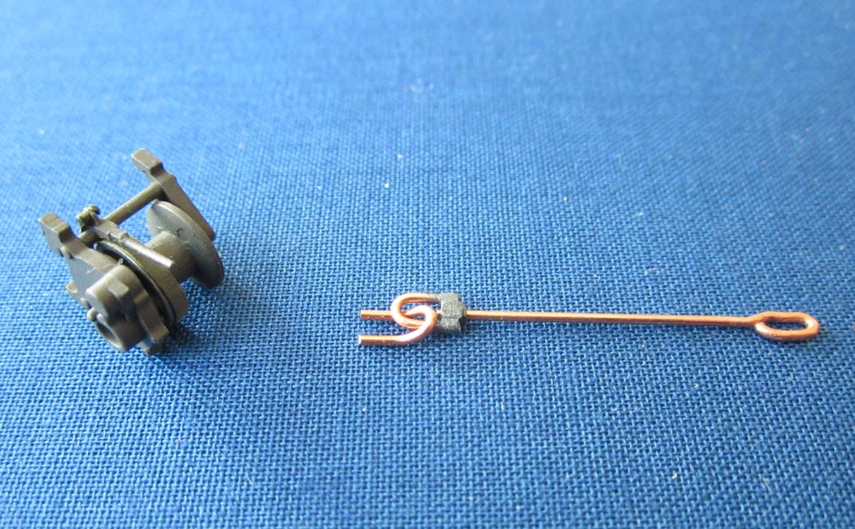 cementing the rest of that into the upper housing hole. A new handle was cut from styrene strip and rod and placed removably between two segments of tubing. (BTW: The platform is lowered and raised by movement of the spade, with the little rollers on parts D60/61 supporting it.)
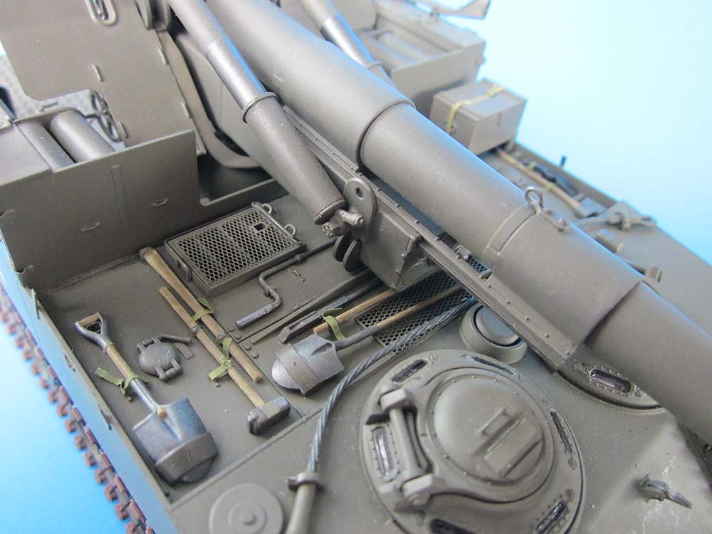
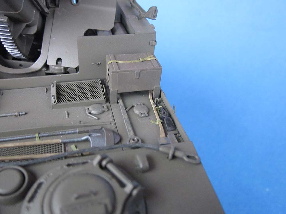
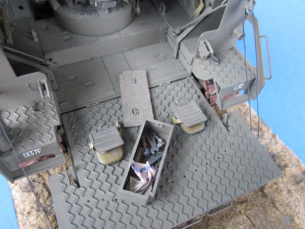
Returning to the hull, the parts of the rear bulkhead (B13) that touch the lower sponson walls are too narrow: not really enough room here for the cable ducts of the tail lights. I managed to cut holes for that anyway and used 0.56 mm solder wire which was continued into the engine compartment. The instructions give the impression that the stowage box block (B7) should be cemented in; if you do that, it'll save you adding the hinge representations on the lower floor that I added from stretched sprue. On the other hand, this part actually represents four separate stowage boxes that look awkward when placed somewhere outside the model as a block, especially as their lids are made from tread plate, and that includes the lid sides, which Tamiya left smooth. So, I cut the box block apart and closed the open sides and bottom, sanded off the 'tread plate pattern' on their tops and filled the 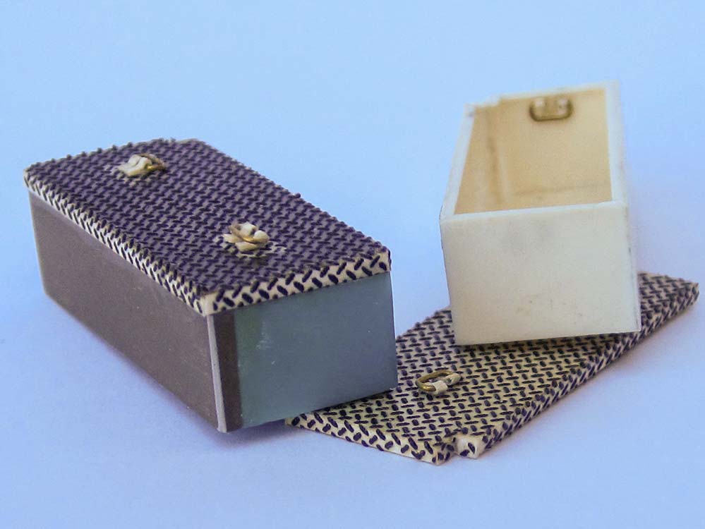 depressions around the handles, as these were not countersunk into the treadplate lids. After adding the 'lid sides' with thin styrene strips all around, Archer decal AR88008 was used to restore the tread plate. New handles were bent from thin brass wire and mounted in strips of very thin styrene bent into a 'd' shaped cross section. And then AMS got the better of me and made me construct one open box with its inside carrying handles …
The large sponson stowage boxes C24,36 each have four indentations on their inner sides indicating 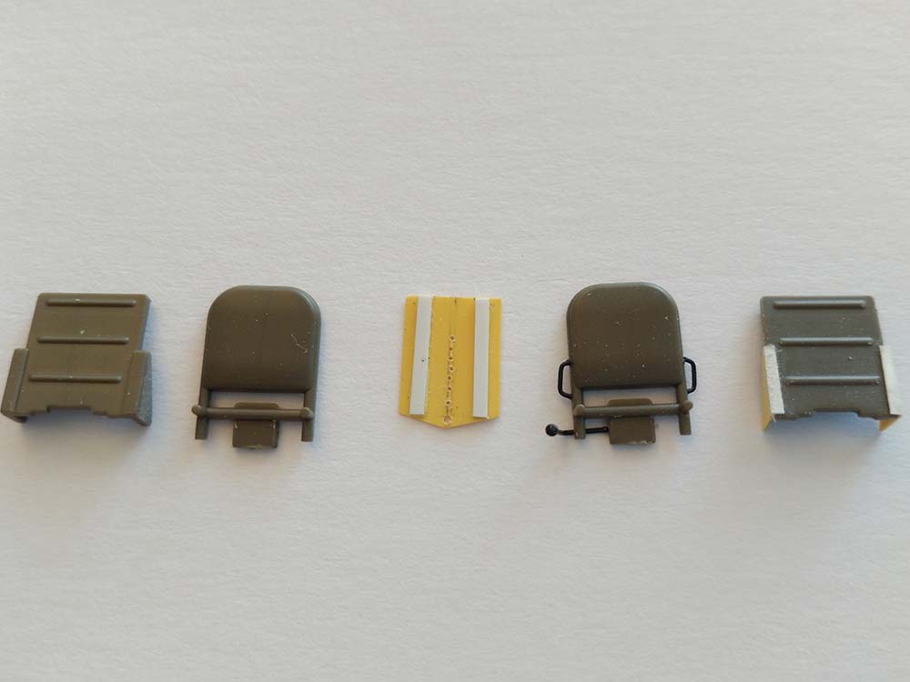 where holes can be drilled for different height installation of the crew seats, while the instructions tell you to mount them all at the same level. I replaced the corresponding locating pins on the seats with squares of plastic sheet that allowed me to place the seats as I wanted them, and also replaced the locking pin handles at the bottom of the molded-in seat mounting plates. Two more of these mounting plates were scratchbuilt to be used on the tailgate. All seat pads had their lateral hinge triangles replaced with thinner ones from plastic sheet, and seat belt eyes and adjusting levers from stretched sprue were added. Seat belts were made from onion skin paper painted with water colors, their locks from thin wire and plastic strip. –
 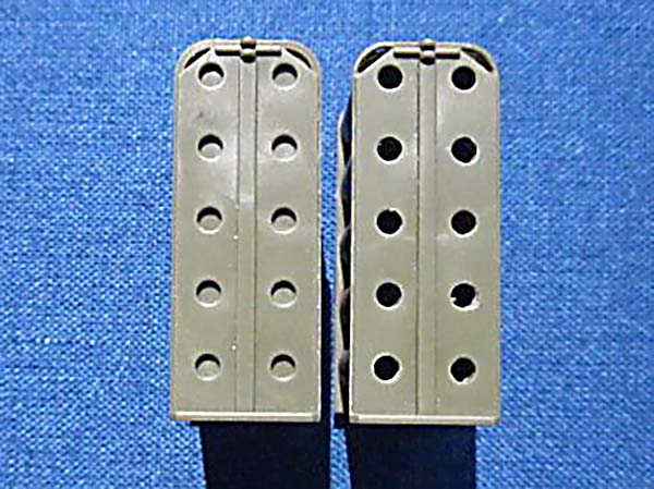 On the lids of the sponson stowage boxes, a total of eight small flat molded squares were removed to be replaced by sheet brass and aluminum supports for 'universal rifle racks' by Tiger Model Designs; two more of these went on the rear sides of the trunnions. The 'ready rounds containers' C6/7 had the holes for the projectile tips drilled out (projo lifting eyes sticking out here would look great) and the top covers thinned out as well as locking handles plus securing PE chains added.
The outside weld beads on the fighting compartment walls were improved by cementing on stretched sprue softened with liquid cement and structured with a knife blade. Replacements included stretched sprue tiedown eyes all around and the tarpaulin bow brackets on the corners from sheet brass with styrene stoppers at the bottoms of the lower ones.
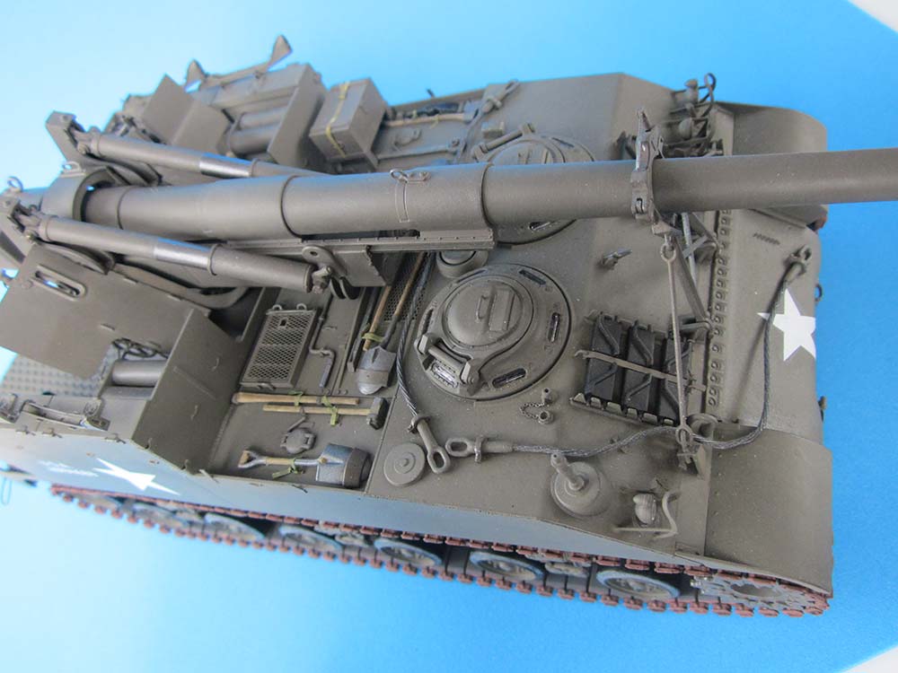
 The large air outlets in the engine deck (B15) each received three sheet braces inside (including a 'starter crank guide' on the right hand side) and some tiedown eyes on their thinned down slanted 'covers', together with copper wire handles at the opposite ends. The kit-supplied PE mesh covers sit in sheet metal frames on the prototype, so I added these from strips of printer's aluminum. Some of the tool positioning holes were closed, a number of tiedowns replaced; weld beads from stretched sprue had to be
 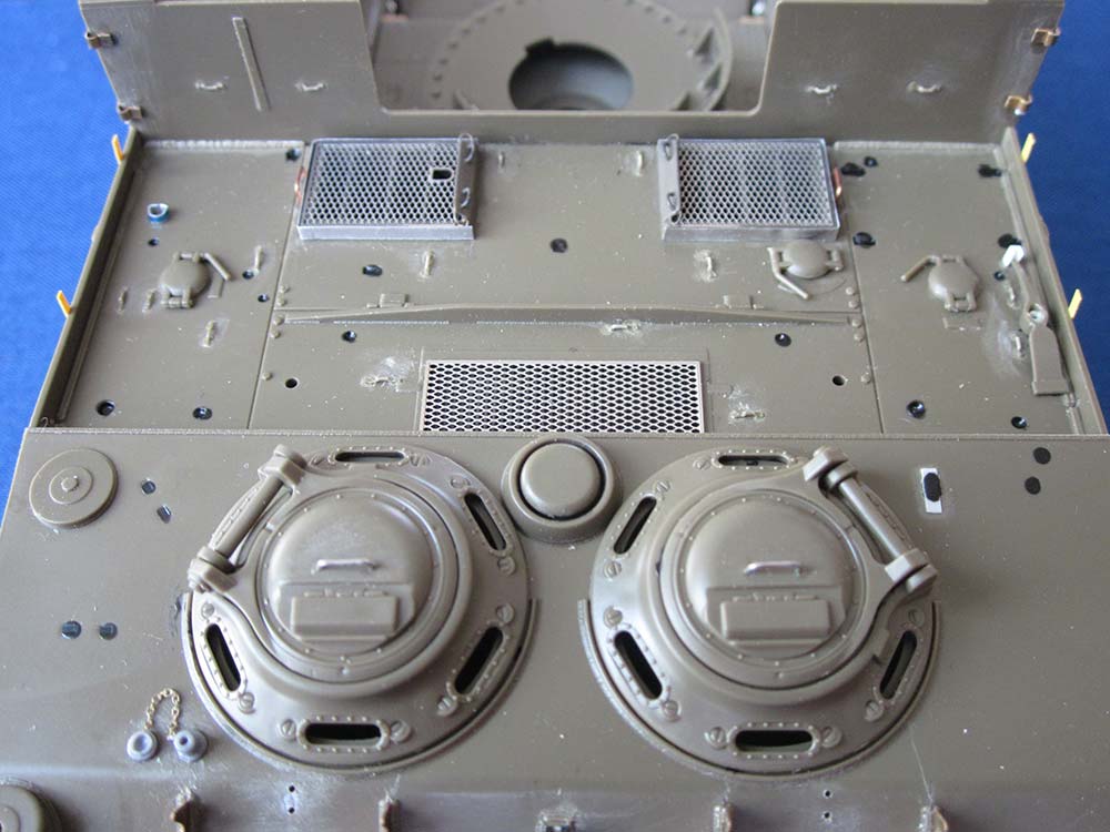 made along the front and rear sides of the lateral cover plates. The 'drain holes' shown on the side walls were drilled through to the engine deck; in the middle between them and above the rear ones, narrow strips were cemented to the walls, together with tiedown eyes, as stowage points for tarpaulin bows (tops to the front).
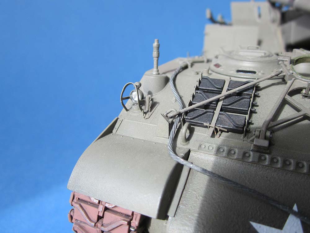
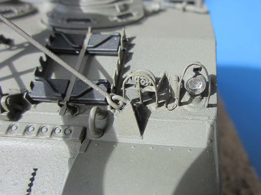
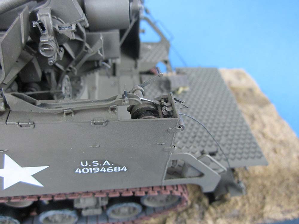
On the glacis, the engine fire extinguisher releases had to be added on a small platform of styrene strip: two layers of 0.5 x 2.5 x 4.5 mm strip wrapped with very thin sheet supplied the body that was then sanded to shape, the T-handles were made from stretched sprue. The cupola hatches had their molded-on handles replaced with wire ones, their right hand hinges had tiny holes drilled in on their top rear to represent what their hold-open rods would go into. The clear plastic view blocks had their sides painted black before being mounted with white glue. The headlights received aluminum foil reflectors glued in, PE brush guards from spares were added around them and received plug stowage tubes from styrene rod plus PE chains from spares. 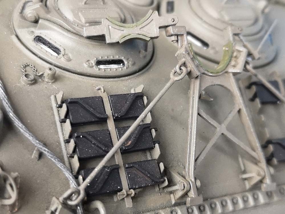 The new searchlight socket came from TMD, the 'comb device' on the transmission housing from the scrap model, as did the spare track holders. The track shoes here are leftovers from my AFV Club model's tracks. Tow ropes were made from annealed push bike gear shift cable (0.8 mm dia) that was superglued into the kit's rope eyes that had had their notches filled before being drilled out again. I used the kit rope stowage brackets.
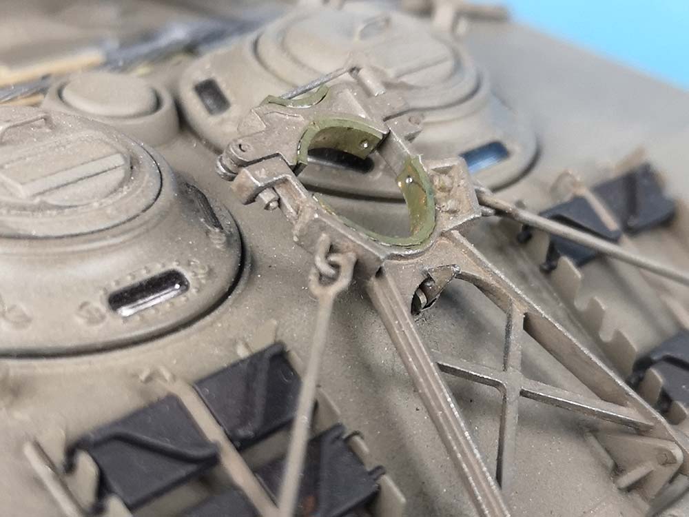 The front gun travel brace was basically OK, but I further detailed it so that now its top could be turned upside down to fit the 8" howitzer barrel, should the need arise. Later, it turned out that its opening is way too wide, so I cemented in 0.5 x 2 mm styrene strips as 'lining'. The travel brace's arresting hook (D9) was replaced with a working construction, and the lateral brace rods had the 'snap on' gaps in their eyes filled after mounting.
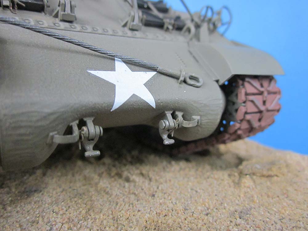 Stretched sprue weld beads also had to be replaced at the glacis sides, as the kit ones were, of course, beside the seams. For some reason, I didn't succeed in getting a tight fit of the front mudguards to the transmission housing. On that part, the 'stirrups' next to the tow hooks were thinned down, while the hooks themselves were cut off their braces so they could be mounted with separate bolts and cotter pins on brace replacements. The running gear presented no problems, but I postponed mounting the eccentric idler wheel axles (D19) because after cutting off their positioning rib, they can be rotated, thus allowing to adjust the tension on replacement tracks.
Gun
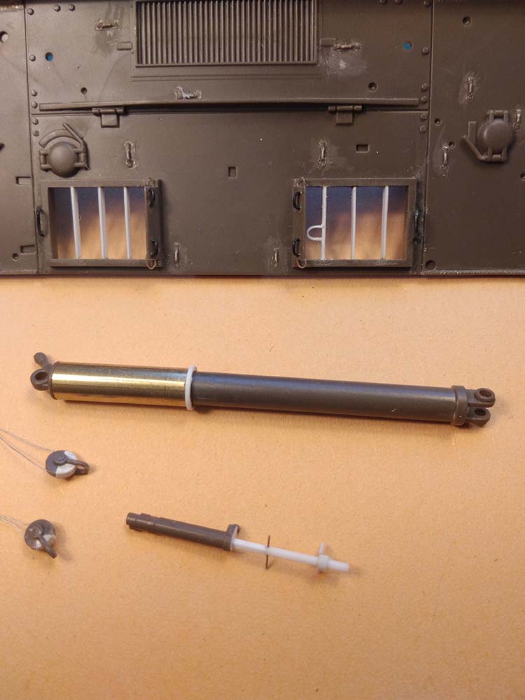
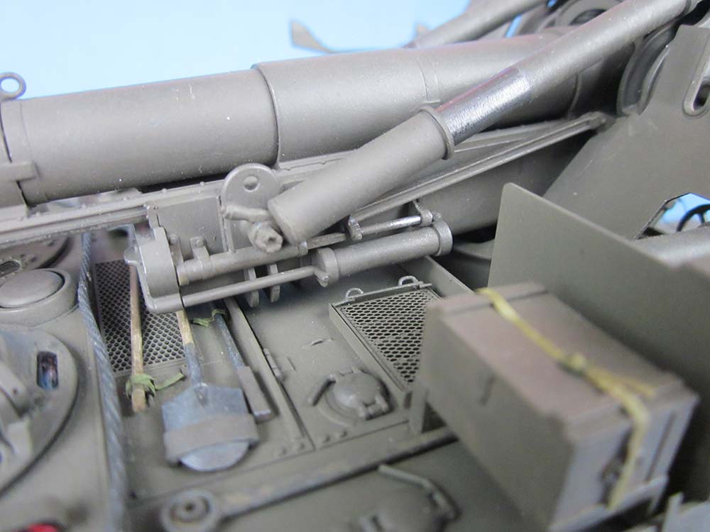
 Turning to the gun and its mount, the first necessary correction was thinning the cradle's rearmost part to sheet metal thickness. Next, I couldn't resist making the variable recoil mechanism (the steeper the angle of fire, the shorter the recoil) fully moving, beyond Tamiya's cleverly constructed sliding actuating arm: The cylinder rod of part G18 was cut off and a hole drilled into the cylinder, which was then covered by a new end plate with a square opening. A new rod from square styrene strip lengthened by styrene rod of identical diameter had a tiny hole drilled into that joint. A new rear rod guide was scratchbuilt, and then the actuating arm could be installed with stretched sprue hinge pins. The equilibrators look very nice, with the brass tubes having the correct difference in diameter to the plastic cylinder rods. The 'rings' around these rods, however, had to be sanded off; instead, 0.25 x 0.5 mm styrene strip was cemented around the upper ends of the brass parts.
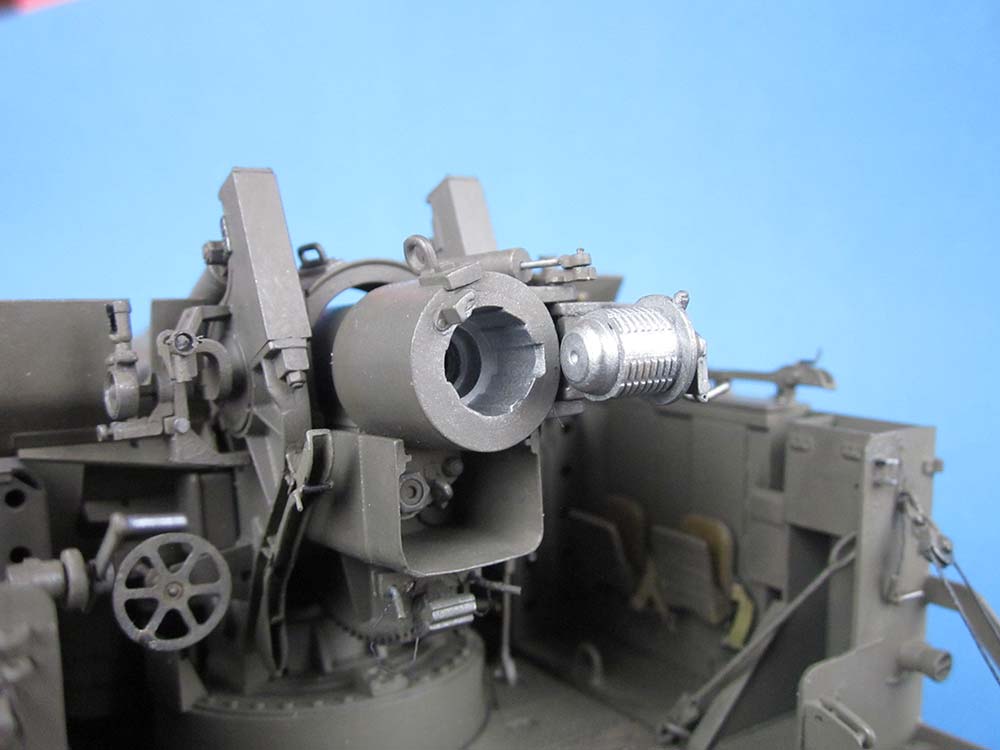 As for the gun itself, I added a 'bore' from a drinking straw and made the breech movable by drilling through its hinges and replacing the rod of the drilled out support cylinder on its top. Further holes in the respective parts allowed them to be joined movably with pieces of stretched sprue. The 'roller' on the locking screw bearing plate (G60) would point at 10 o'clock on an open breech, while the kit gives it fixed at 12. No problem – all there is to do is cut off a bit of the part's upper positioning ridge's half so it can be turned as needed and even be mounted movably after a slight shortening of the screw. I could, however, stop myself from cementing in 'interrupted screw' parts into the block.
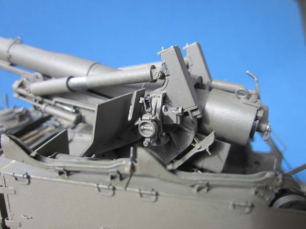 Part G26 is a very weak rendition of Panoramic Telescope M12 (google that and you'll see why): It has an eye piece that is tiny compared to those of the gun's other two optics, and it doesn't have a lens. Instead of trying to correct (i.e. scratchbuild) the upper half of the scope, I cut it off just above the 'rim' of the bottom
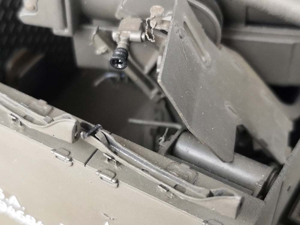 half and drilled that out before cutting in a vertical gap, thus showing the periscope mount empty. The direct sight scope, D90, was also left off, with two styrene tube slices representing its mounting rings. My model will be preparing to leave its fire base or just arriving there, with its optics stowed, except for G7 on the right, which is joined to the right trunnion via a short plastic rod, so it elevates. The gun shields C27,30 are rather thick, with beveled edges. Upon the top right, I placed a contraption of unknown purpose from sheet brass, styrene rod and PE chain, 'connected' to the molded-on cable with a piece of stretched vinyl sprue.
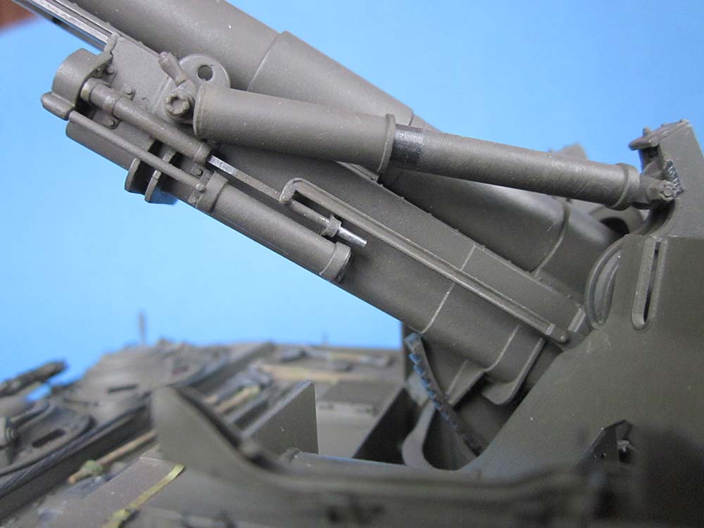
' Gun Breech Anchor Rods' were bent from 0.75 mm copper wire and connected to fixing points from the same material on the sponsons.
 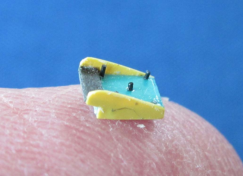 The David Doyle book shows that there were (at least) three different contraptions to arrest such rods on the cradle, so I installed a less complex version than on my AFV Club model. – There's another part here that keeps the trunnion fixed to its base which the kit doesn't contain: A 4 x 4 mm square of 0.9 mm sheet, with thin side walls of 2.5 x 5 mm sanded to a triangular shape plus a strip of 0.5 x 1 x 4 mm make up a 'catch' that has a step at its front which goes over the trunnion bottom plate's rim. Its prototype is attached with five bolts that I added from slices of hexagonal rod after taking the photo.
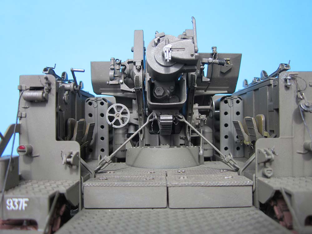
 The two additional crew seats can be mounted and dismounted on the rear platform by inserting tiny 'mushrooms' (made from stretched sprue held near a flame) on the rear of their scratchbuilt mounting plates into the 'keyholes' and sliding the whole thing downwards to a position where the arresting pin can slide into its hole (and no, that one doesn't turn on my model).
Running gear and tracks
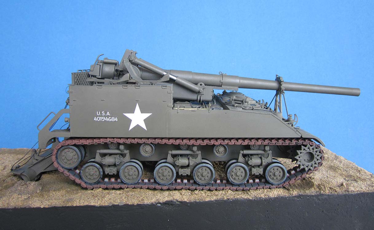
Putting together the bogies and all wheels offered no problems. There is no possibility of articulating the running gear, everything can only be cemented as for a vehicle on a concrete slab. I replaced the kit's very good-looking one-piece vinyl T-80 tracks with the indy-link ones by Kaizen, a Hong Kong manufacturer. As can be seen, they look highly realistic, right down to the small ridges on the outside of the end connectors, and they are very strong because of their brass wire track pins. On their box, however, it says 'Just be patient', so consider yourself warned.
E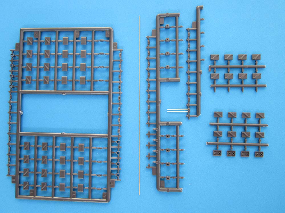 ach link consists of 9 (nine) parts: right and left track pad inside and out, guide bulb upper and lower, end connectors, and track pin. The first exercise in patience is cutting the parts from the sprue and cleaning them up – that's 17 cuts per link!
 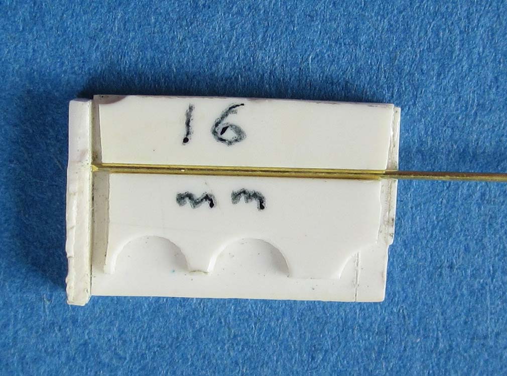 The next test of your patience is that you have to assemble all these small parts – it took me a while to figure out how to cut pieces of sprue with four outer pad halves and then place them onto ones with four inner ones before applying cement. The two parts of the guide bulb were also glued together with the small outer element still on the sprue. While the cement on the 3 'inner' units sets, you can cut the pins from the included lengths of straight wire; I built a small jig to make measuring 16 mm easier. The pins are a press fit in the end connectors, and that requires inserting them with pliers – you also have to give the all of their ends a swipe or more with a file before they will cooperate.
| Painting/Weathering |
Remember what I wrote at the beginning of this text: I don't like painting, to put it mildly. A base coat of Games Workshop Chaos Black from the rattle can, followed by Revell's Nato-olive 46 overall and a few red spots for the fire extinguisher release handles and the road wheel grease fittings, plus some graphite wear marks was all I could bring myself to.
The tracks were primed with Chaos Black and then airbrushed Revell Airbrush enamel Rust. The inside track pads were brush-painted Revell Dark Grey, the guide teeth sides with a silver marker pen. The outside chevrons then received a little graphite from a pencil and the whole thing a wash of black gouache.
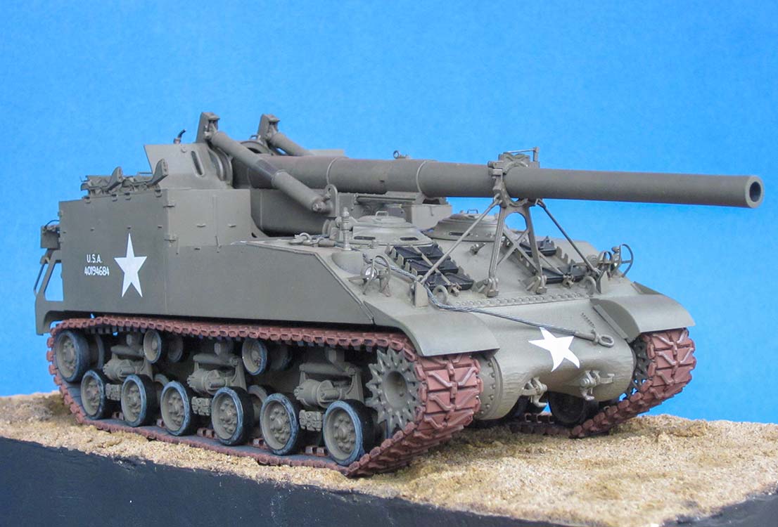
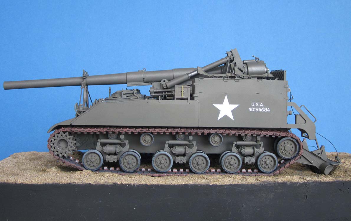
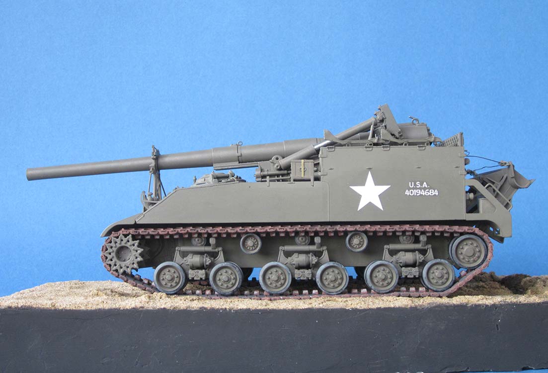
Markings are from the kit, but I depicted 'Courageous Confederate' in a state before that name was painted on (and before its rifle racks were removed). Another small Tamiya omission here: The unit markings '937F' and 'C30' are correct for the mentioned vehicle and have to go to its rear steps, but the instructions don't show that. 'Aita's Ankies', the other marking option, is for a gun of the same 397th Field Artillery Battalion, but that prototype seems to have had no comparable markings that could be seen in the photos of the Doyle book.
| Conclusion |
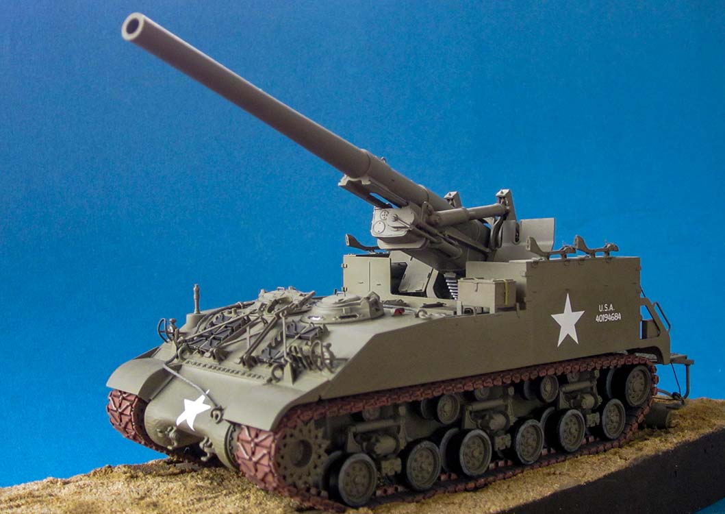
As I said in the introduction, I built this kit to compare it to AFV Club's effort of the same subject.
First off, that kit is about half the price of Tamiya's, while both are not free of inaccuracies. That said, I think the difference in price is justified. The short and incorrectly thick gun tube and the too low mounting of the whole gun assembly make the Club's model look awkward and demand, at least from a rivet counter like me, extensive correction work. The Tamiya model, in contrast, gives the correct overall look right out of the box. The detail omissions it has are rather easily remedied provided one feels the urge to do so – I suppose most modelers won't even note them. In addition to this, you get twenty projectiles plus their decals in the box, ten of them with a fuze, the others with a lifting eye so they can be placed on the included pallet alongside four propellant charge tubes, again with markings. Eight crew members round out what will make an instant diorama and so put the Tamiya kit even further ahead of the one by AFV Club.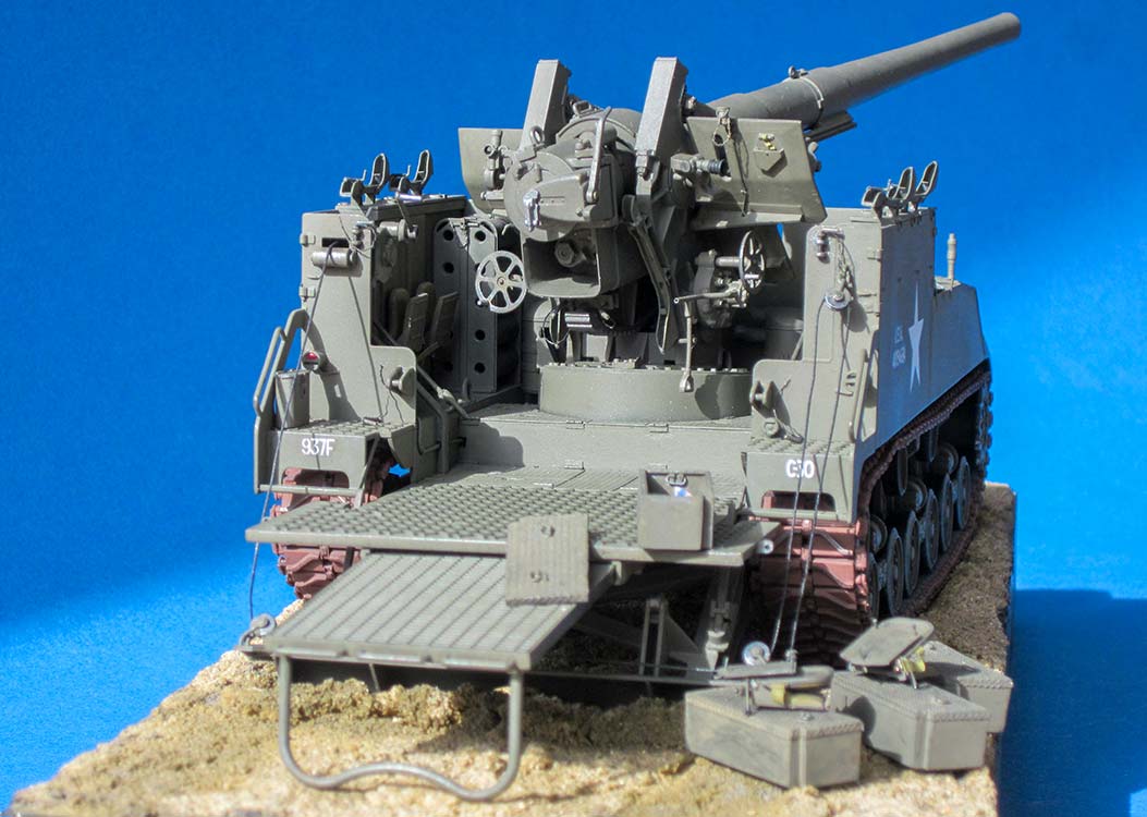
| Price / Value: | ***** | Fitting: | ***** |
| Detailing: | ***** | Skill level: | ***** |
 |
 |
 |
 |
 |
 |
 |
 |
 |
 |
 |
 |
References:
- TM 9-747, september 1947, und 9-1747, october 1947
https://de.scribd.com/document/139525882/TM-9-1747-155MM-GUN-MOTOR-CARRIAGE-M40-M43 ; - toadmanstankpictures.com M 43
- primeportal.net M 40
- http://www.vgbimages.com/AFV-Photos/Arkansas-VFW-American-Legion/ARNG-Armory-Mena-AR-M40/i-t72rLCN/A
- http://www.vgbimages.com/AFV-Photos/Arkansas-VFW-American-Legion/City-Storage-Yard-Charleston/i-KBfLxS7/A
- http://www.vgbimages.com/AFV-Photos/Camp-Robinson-AR-ARNG-Museum/i-ggQsLD9/A
- David Doyle: "M40 Gun Motor Carriage", Schiffer Publications
© 11/2019 Peter Schweisthal
8064 readers of this build report since 09.11.2019