|
|
|
4.place
at build-report-contest 2009 |
 |
| The original |
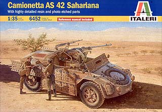
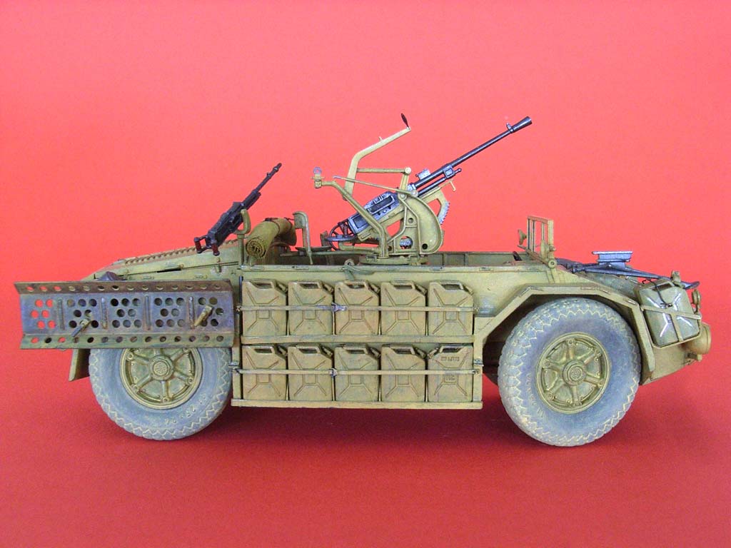
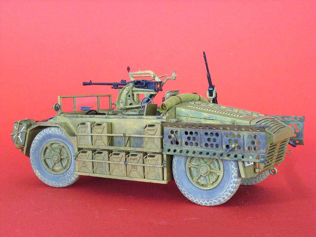
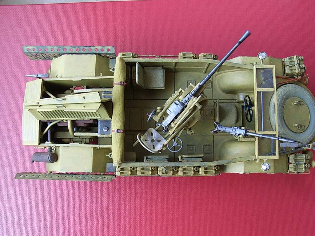
This Italian "Desert Jeep" was introduced for use in North Africa (Africa Settentrionale) 1942. The four-wheel drive chassis was thereby assumed by AB 41 armored car, but without steerable rear wheels. Some vehicles have been used in Russia, and after the war the leftover served under the name "Metropolitan" to the police. Unfortunately no vehicle has survived.
| The kit |
In this version, Italeri has given us a multimedia kit, with resin parts for engine, gear box, radiator and two figures, plus a PE fret from sturdy (0.5 mm) brass for sand channels, steps, and jerry can braces. Both these additions are, interestingly, "Made in China", while the main styrene claims to be made in Italy. Anyway, I noticed that the tan plastic material is different from the olive drab Italeri stuff that I was used to, in that it makes fewer sink holes, and stretched sprue drawn from it "mushrooms" up in a much more useful way when held close to a flame. An extra bonus is a booklet with a good number of prototype photos and additional tips for detailing and painting.
On the down side, there are two parts missing from the kit that really should have been included. One is a PE crosshairs for the 2 cm cannon, as shown on the built up model in the photo booklet and on the box side. The other is a fuel filler. Admittedly, I can't claim to see one in any of the available photos – but I mean, the contents of all those jerry cans have to go somewhere else than the two minute tanks in the engine compartment, right? The weblink mentioned below has a cutaway drawing that shows a large fuel tank in the forward part of the chassis, with a filler neck apparently going somewhere to the left – just where?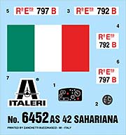
| The build |
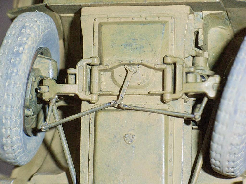
 AMS reared its ugly head right when I studied the instructions for the first time. Valve stems from stretched sprue were a must, and making the front wheels positionable appeared so easy that there was no question I just had to do it: All this requires is to drill through the lower part of the front wheel suspension (part 11B) and then cement its bottom end into the lower wishbone after cutting it from the rest of the part. With a piece of thin wire inserted, this swivels beautifully. The forward drive shaft universal joints received the same treatment, while the steering linkage needed a real thin drill bit (0.25 mm) before it could be cut apart and rejoined with bits of stretched sprue. To its slightly lengthened swivel axle, a retaining ring was cemented inside the chassis.
The instructions mention that the vehicle was developed on the chassis of the AB 41 armored car that had all-wheel steering, and so, Italeri gives us the chassis and suspension parts trees from that kit. Fine – but if the description continues that the Sahariana's rear wheels were NOT steerable, then why did Italeri reproduce this by simply leaving out the order to mount the provided rear steering linkage? Mounted that way, the prototype's rear wheels would have wobbled at will!
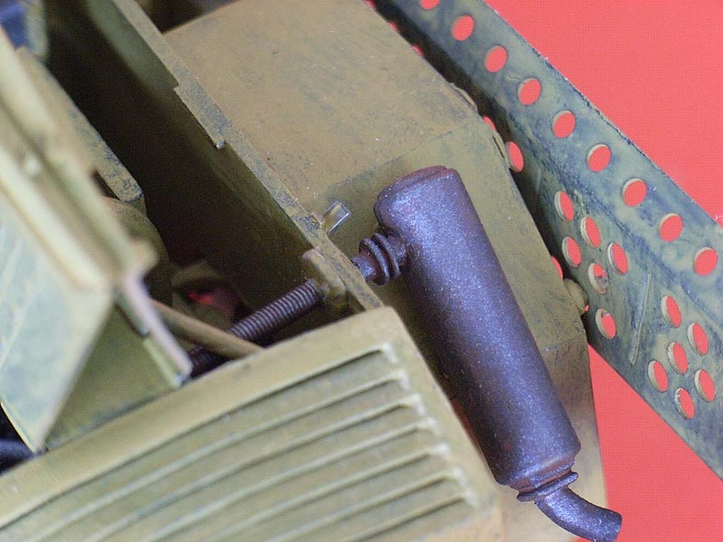
Next step in the instructions was the engine. By this time, I had found a really helpful building report on the web (via Missing Lynx Discussion Forum Axis WW II, february 28, 2007, 1:09 PM): http://www.webkits.com.br/news/templates/news.asp?articleid=345&zoneid=14 It's written in Brazilian Portuguese, but the photos are self-explanatory, and so I immediately understood that it really simplifies construction and painting if you cut down the sides of the flywheel (or whatever the widest part of the resin engine is), as this enables you to insert the engine after mounting the body onto the chassis. I didn't add any detailing to the engine and painted it gun metal, with a strong brownish black oil paint wash, while the exhaust manifold was painted rust.
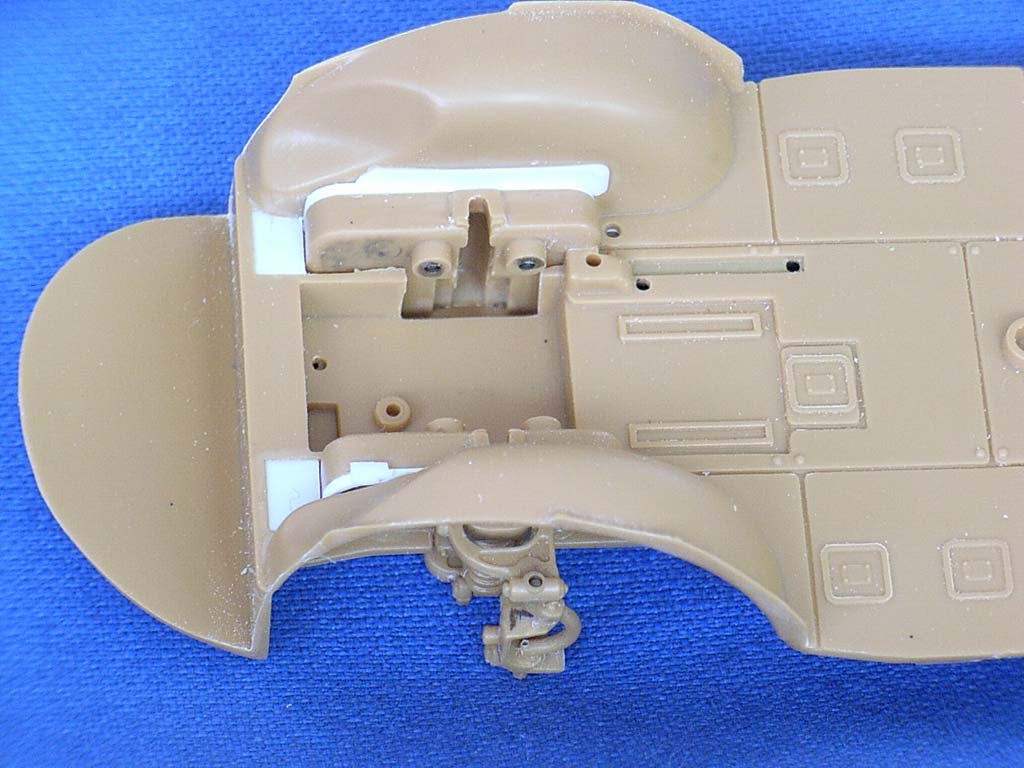 A test fit of the cab bottom plate to the chassis showed considerable gaps between the inner suspension area and the front mudguards. Now SPA, the maker of the car, was a division of FIAT, and the Germans' interpretation of that acronym was "For Italians, Adequate Technology", but I just refuse to believe that anyone would construct a desert vehicle with openings this size for dust and sand to enter, so I closed these areas with sheet styrene. In hindsight, it might have been a good idea to do the same thing in the rear, to protect the engine and radiator.
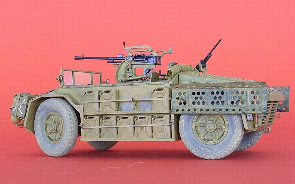
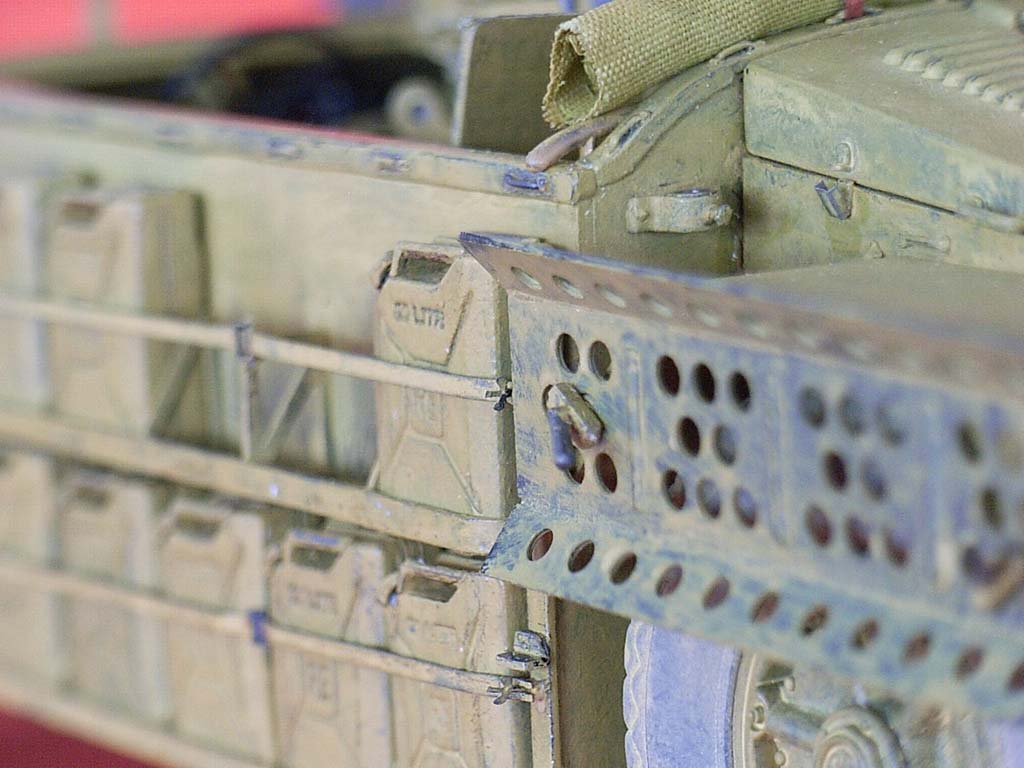
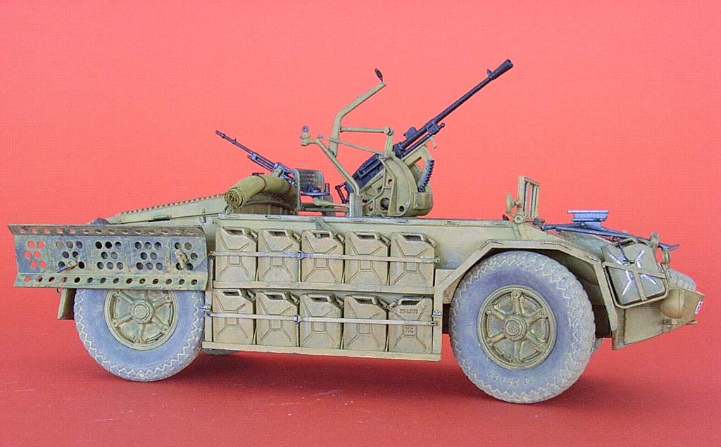
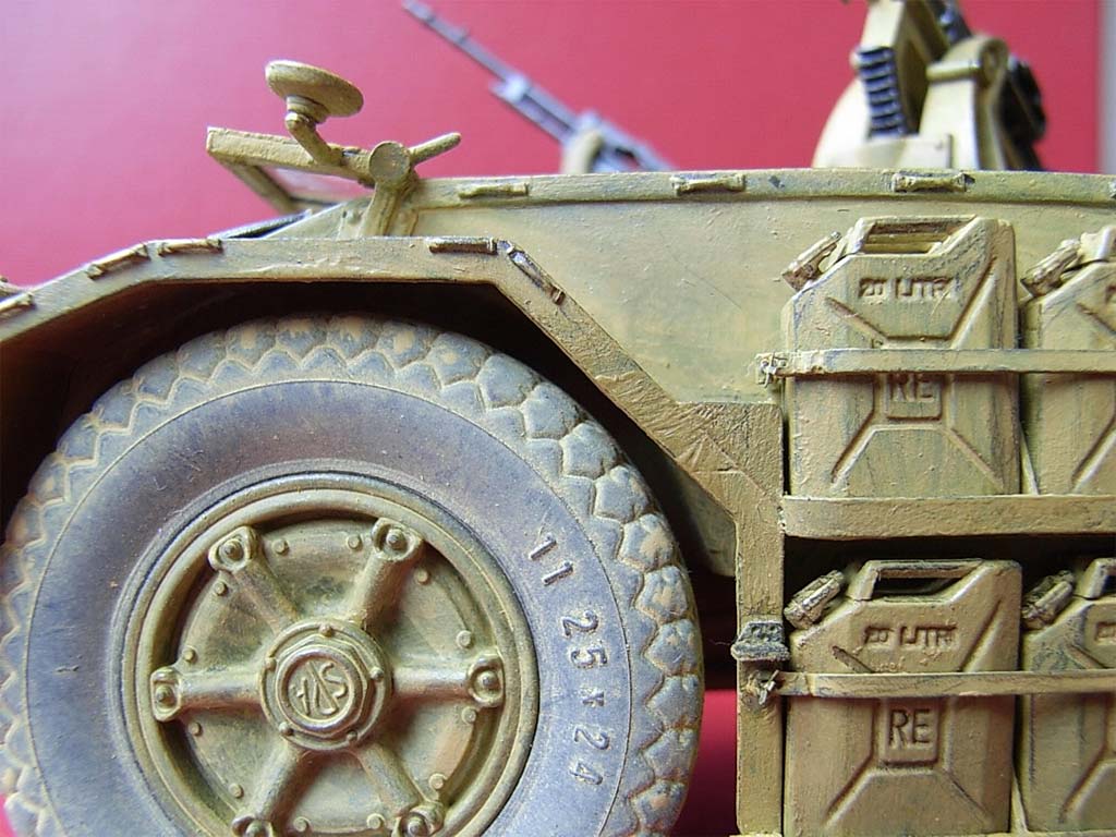
The link mentioned above also contains one prototype photo of the later ABM 41/42 variant with an empty lower lateral can rack, and that led me to a closer inspection of the corresponding kit parts. It turned out that not only were all these cans missing their characteristic crimp seam, but also the racks were much too thick, and there were no empty spaces where the cans bent away from the lateral braces, not to mention the missing gussets between the cans. So, all cans were separated from each other and freed from their rack representations. They then received their double crimp seams inscribed before they had their spouts and handles fitted. (Note that the instructions are very sketchy regarding the spout position: this has to sit on the left half of the can, as seen when pouring, with its thinnest part pointing at the carrying handle.) For excellent photos of all kinds of German cans and their international clones, see sdkfz7.free.fr/ejerrycan.htm .
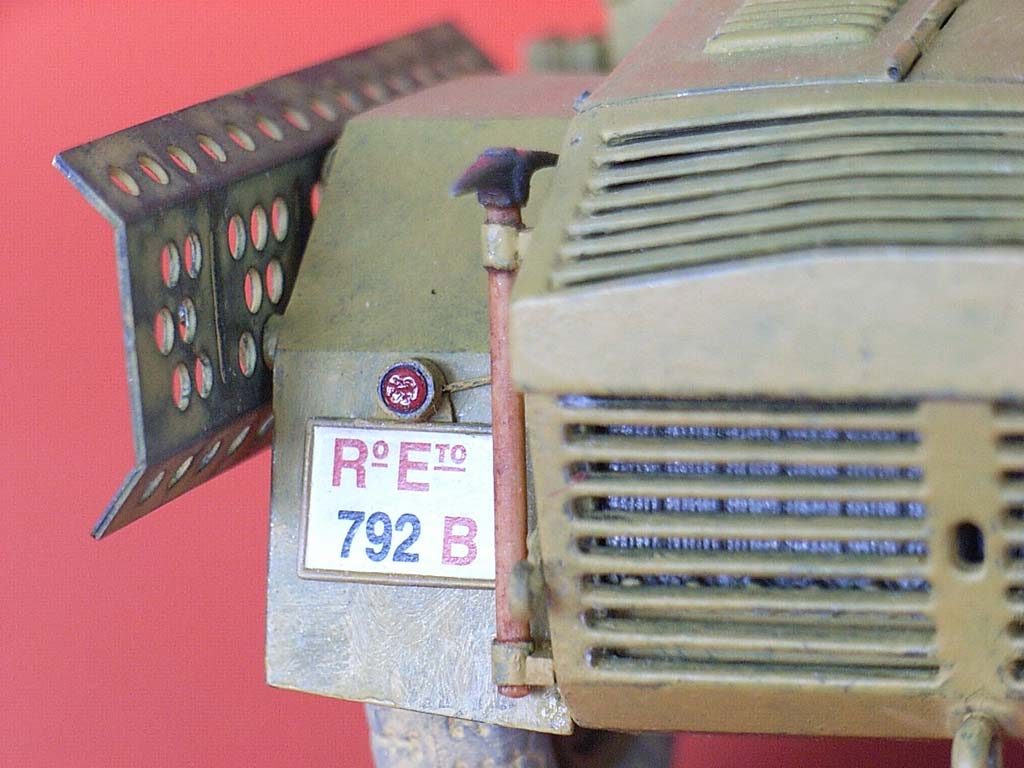
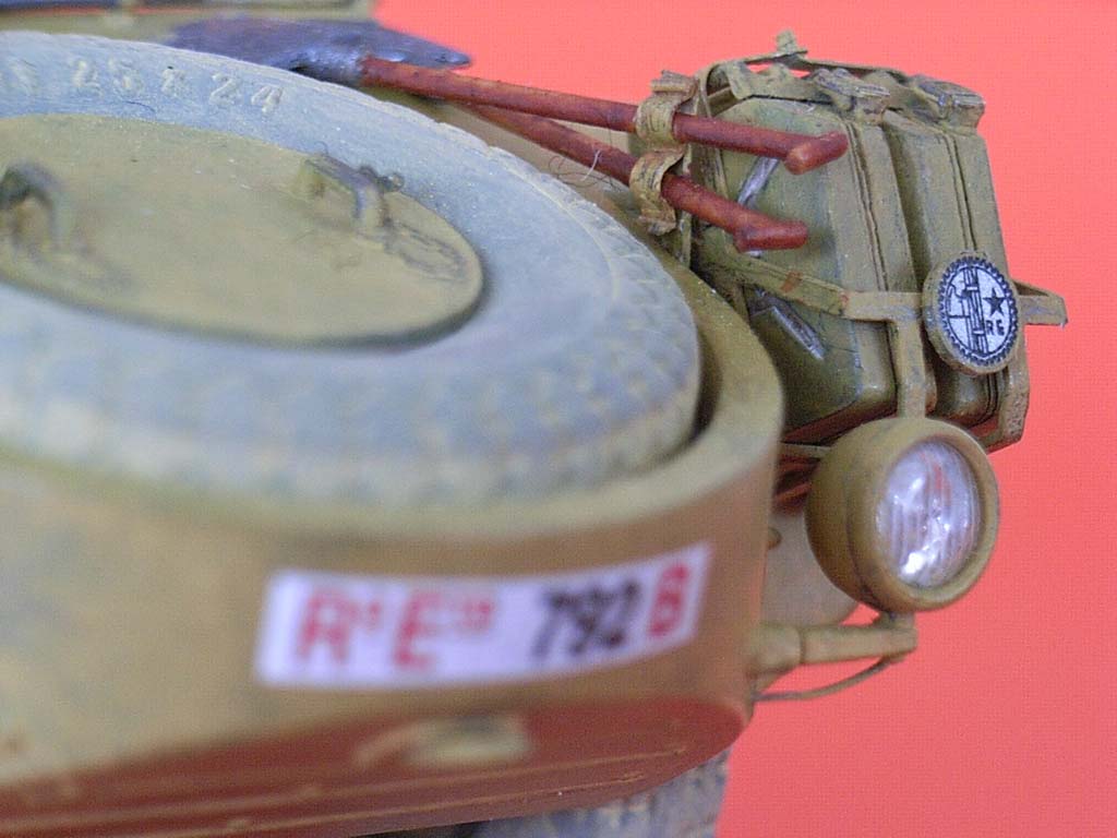
Speaking of clones – this site also confirmed a suspicion I had grown while studying the photo booklet: Italeri correctly lettered the stiffening square on the can sides "RE", but ignored a distinctive feature of the Italian can version, namely that the stiffening "rays" that extend from the square's corners would form an exact "X" when connected through the square. The standard German cans and all their other clones, however, have these rays at different angles which don't render an X. Seems like Italeri either didn't note the difference or didn't want to go the extra mile of cutting new molds. – And I won another victory over AMS by not even trying to correct this!
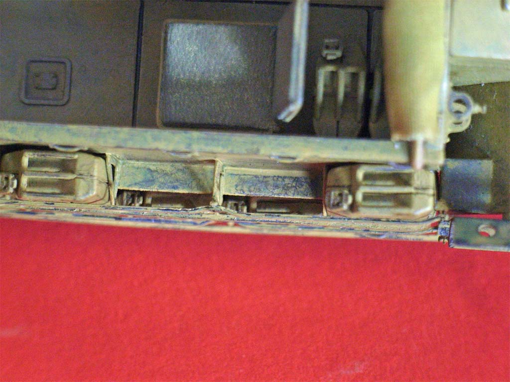
Now the cans had to be installed. Close scrutiny of all available prototype photos and a comparison to the kit parts showed that Italeri has made the side panels and the mudguards in slightly wrong dimensions: Taking the scale cans' height of 13 mm as correct, the 29 mm height of the sides is too little to accommodate two rows of cans plus correct headroom above each, especially with 1 mm thick rack bottoms. Besides, prototype photos show the bend in the mudguards above the upper rack's bottom brace, not in line with it (interestingly, this mistake has also been made in all available plans of the vehicle).
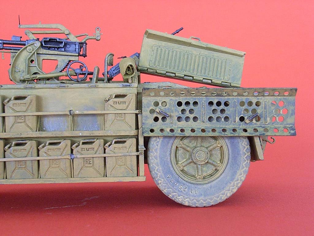
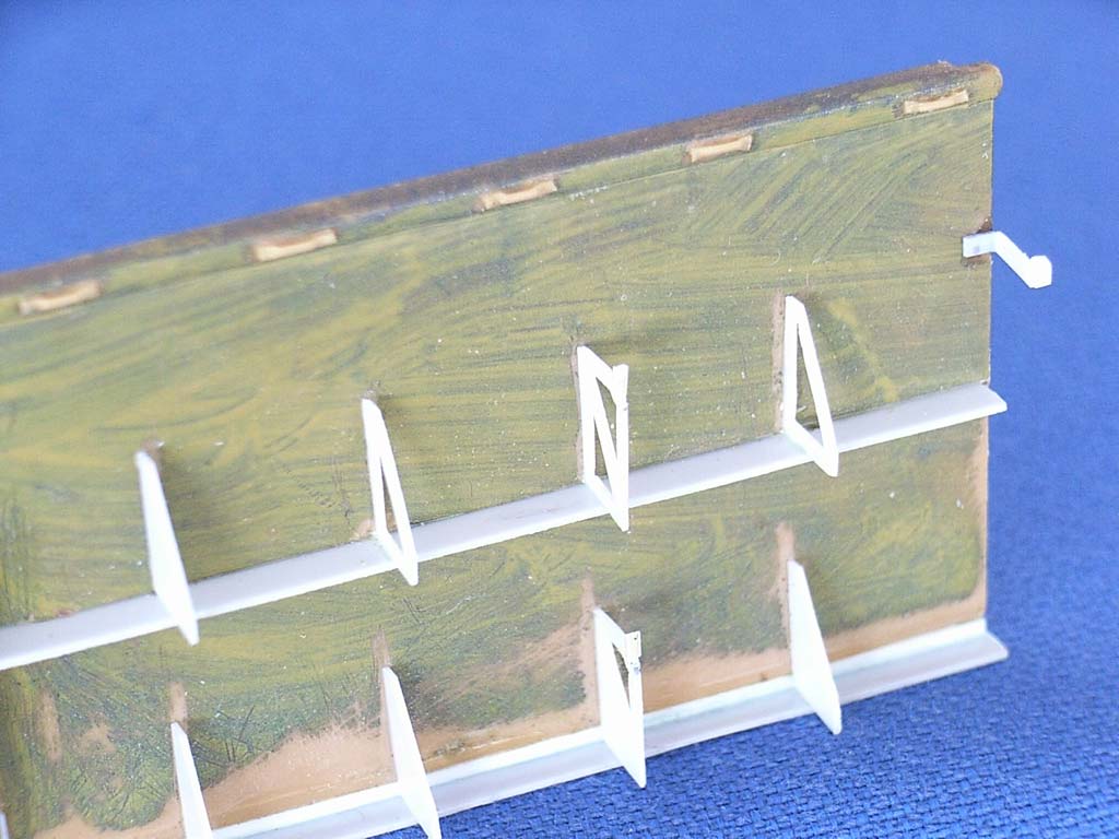 To get closer to the photographic evidence, I cut off the rack halves at the bottom of the side panels. The next measure was to cement .75 x .75 mm styrene strips to the side panel and mudguard bottoms. I had planned to replace the racks with full-depth strips of 0.3 mm sheet to be cemented below the sides. Staring at the photos, however, started me wondering how a can could be extracted from the lower rack, with the upper one so close above it: The bottom rack brace seemed to have at least the height of the headroom above the cans, and if you've ever tried to haul a full 20 liter/5 gallon can, you know you'd better get a good hold of it! Which led me to surmise that the cans had to be canted outward to be lifted out. And that could only be achieved by making the bottom strip of the rack about half as deep as the cans. Hmmm. But the faint shadow image of the empty rack in the mentioned photo seems to bear this out (plus, my rack construction wouldn't collect sand), so that's the way I did them. Figuring that it would have simplified production while also saving material, the upper rack parts were made to the same specifications.
The racks received four plastic sheet gussets each, one per rack with a different shape to bear the hinge for the upper braces. The bottom braces were made from plastic strip the thickness of the PE parts. Note that the bottom brace of the lower racks is fixed to the mudguard outsides, whereas the one on the upper racks bends inward as molded by Italeri. I toyed with the idea of making the PE upper braces working, but won the fight against AMS and only bent and shortened them to fit new securing points that were detailed with Aber wing nuts. While I had these out, I also added two of them to the spare tire cover plate on the bow.
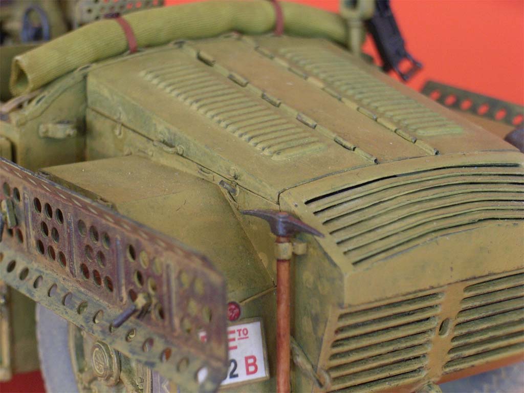
As for the engine hood top, the instructions suggest cutting off the lateral louvered parts and cementing them upright to display the engine. Instead (AMS!), I started by drilling through the front and rear two hinge sections with the trusty small drill bit. I then separated the hinge parts one by one, alternating my cuts between center and lateral cover. After cleanup and insertion of stretched sprue, this rendered movable louvered lids. (But I did manage to resist the urge to open all the louvers !) The hood side walls have two fixtures each that in reality are clamps; their upper parts were cut off and cemented to the movable lids, with tiny pieces of lead foil giving the impression of real latches. I left off the stowage boxes on the rear fenders.
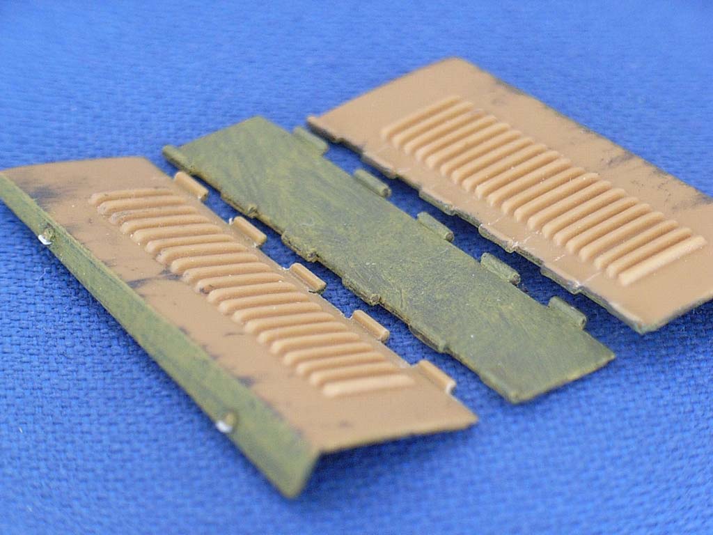 And when I tried to dry fit the engine compartment walls, I had to file down the end of the exhaust manifold a little to get the right hand side wall into contact with the cab; maybe the engine hadn't landed in an ideal position. The real problem, however, arose when the resin radiator refused to fit without shifting the whole compartment to the left, and it took me a good while to find out that the locating pins at its bottom were offset and had to be cut down to obtain a correct fit. Another photo from the mentioned article on the web showing the radiator cover was self-explanatory, too – scribing the upper ventilation slats is easy, and it is just as easy to fully separate them from each other.
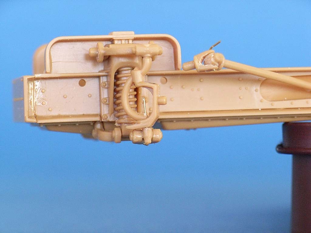
The next shock came when I tried to install the hood top with its movable wings: folding up was impeded by the ridge on top of the cab rear wall that protruded into their way. More careful study of the prototype photos showed that the front of the hood top is more or less flush with the top of the cab rear wall. To achieve this on the model, the hood sides were broken off again and a strip of sheet styrene cemented on top of the positioning ridge at the cab wall. – Instead of trying to remove the mold seam from the exhaust connection to the muffler (1 H), I replaced the center portion of this part with a piece of steel spiral spring.
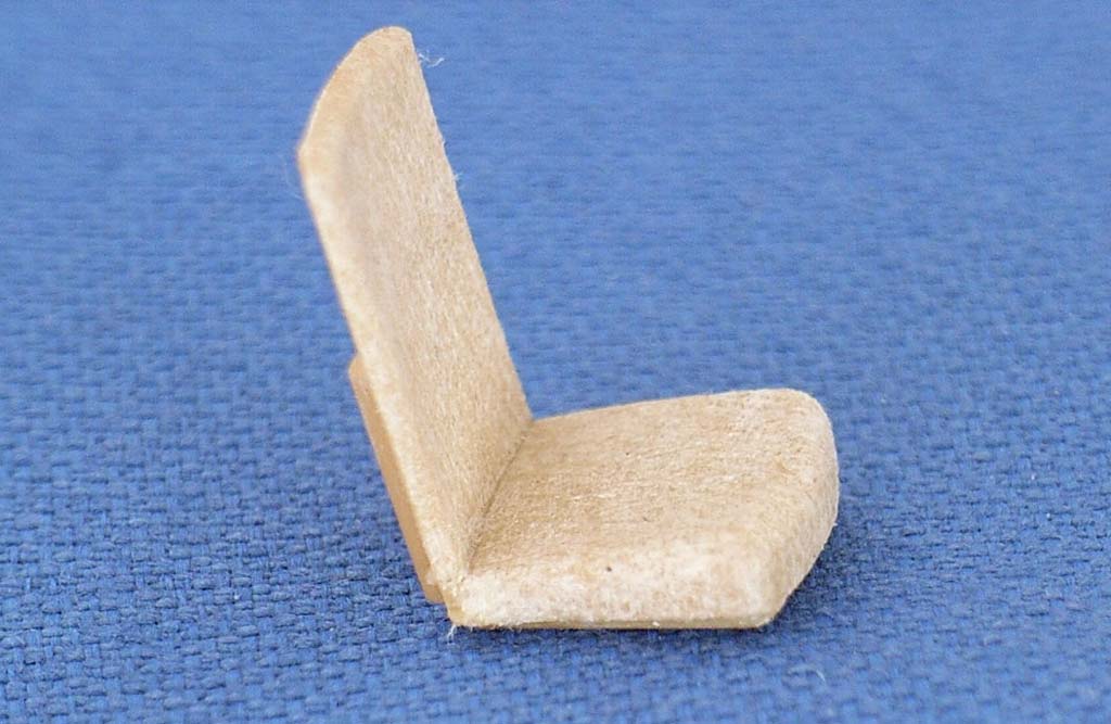 All around the vehicle, there are tiedowns for fastening the canvas roof and equipment. These were all shaved off and replaced by separate tiedowns from stretched sprue. At the same time, I found out that the triangular steps on the slopes of the mudguards (parts 19, 20 G) fit much better when their positions as given in the instructions were exchanged. All seats received a "fabric" covering from a single layer of paper handkerchief, affixed by dabbing on thin liquid glue with its applicator brush.
As for the can racks on the front mudguards, the parts over the can tops set me thinking: Quite clearly, they couldn't be integral parts of the lower cage, as that would have required some severe bending every time a can was to be moved. So, I cut off the PE parts above the lateral eyes and substituted thin aluminum strips on one rack. These are hooked into the lateral eyes and have sufficient play where they meet at the top. On the other rack, this construction must have broken and been discarded somewhere in the desert, so the cans on this side are held in place with pieces of wire. As cans carried here had their stiffening ribs painted white in almost all photos, I presume that the Italians marked their water cans that way, and painted my fender loads correspondingly. The disc added on the top of the left frame appears lower in the photos and even in the paint schemes of the photo booklet, so it was cut off and cemented against the rack.
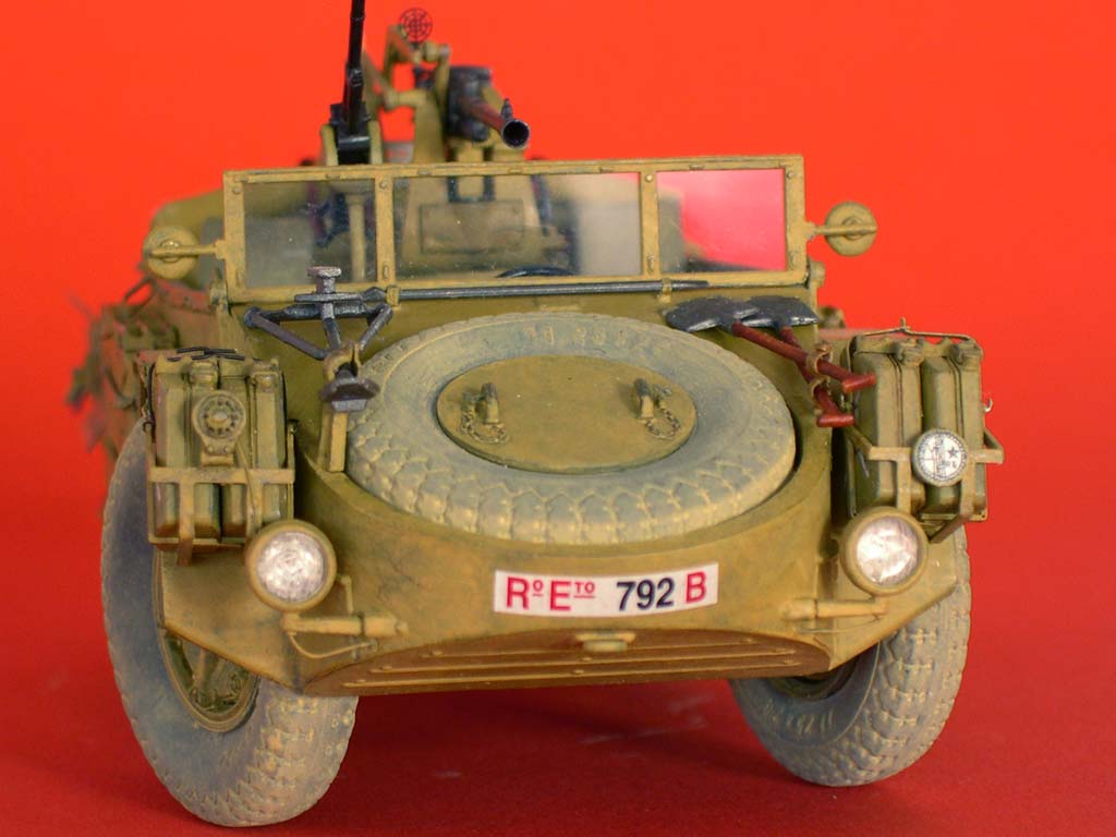
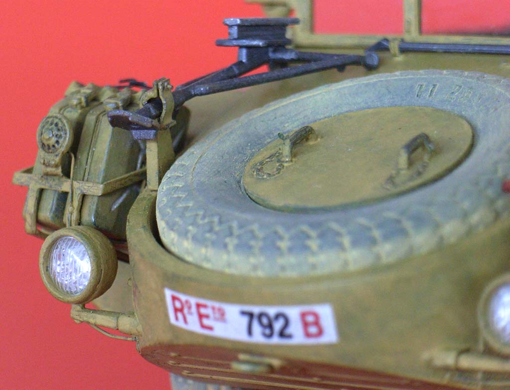
And then there were the headlights. Italeri gives you the housings and two different fronts: "cloth-covered" or ribbed "glass", but all made from the kit's tan plastic. No real choice in my eyes, so I drilled out the "glass" and replaced it with scribed thermoformed acetate. The reflectors had thin aluminum foil white glued inside, and electrical conduits were added from stretched sprue. Another small triumph for AMS, just as the horn mounting brace from sheet brass with a stretched sprue electrical lead on the jerry can rack.
Fixing the front hood on my model took some strong clamping. The stowage brace of the MG tripod (45 G) had a clamp part added. I also scratchbuilt a support for the spade handles, as a picture in the photo booklet shows them not lying flat on the hood, but suspended higher up. Another look into that booklet showed that the "reflector" on top of the license plate holder actually was a tail light, so this was added from a piece of styrene tubing, filled with tinted white glue and "cabled" with stretched sprue. I managed, however, to resist AMS's urging to install the license plate holder in a truly vertical position.
The sand channels are etched parts. AMS, of course, promptly noted that the short etched lines in the center sections are wrong in that they should be raised, providing a grip for the wheels. Which in real life would have been achieved by indenting the back side of the channels in the appropriate places, so I took a screwdriver and a small hammer and created the necessary hollows there, thus also minimizing the front side etchings. These were then built up with thin rolls of epoxy putty.
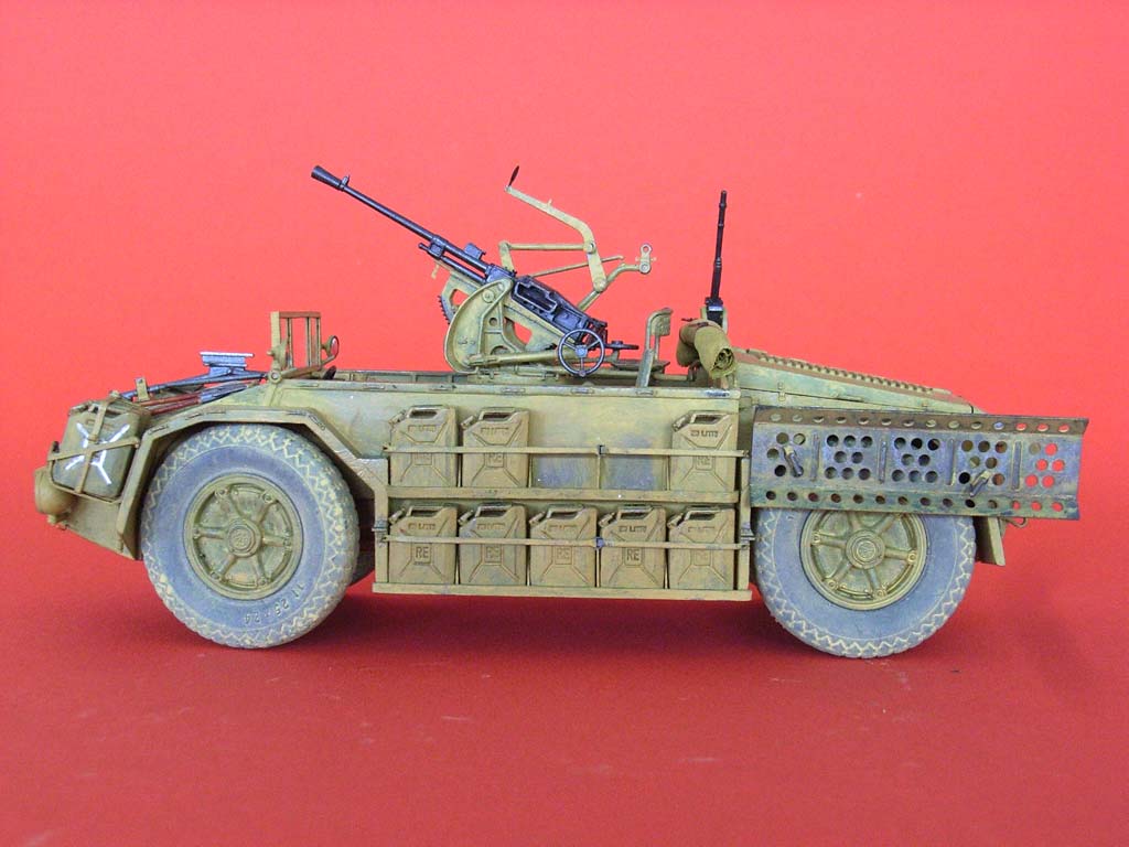
The cannon was built from the box, keeping it movable by using the hot screw driver method. The PE crosshairs were donated by a generous fellow modeler. The gun proper was painted Humbrol Metal Cote Gun Metal, its carriage like the vehicle.
| Painting/weathering |
All areas of the vehicle received a base coat of Humbrol 33 matt (metallic gray), applied by handbrush. This was then brushed over with Revell 16. The seat upholstery got a slightly greenish touch added, the shovel blades remained metallic gray, with brown handles.
The vinyl tires were "painted" by putting them into a plastic bag together with some scrapings of suitably colored pastel chalk and shaking the mixture. Excess chalk was then rubbed off. The cab canvas cover was fashioned from thin silk fabric that was dyed with water colors. Its tiedown straps are from paper, with buckles shaved off the kit part.
The windshield had been left off until last. After the frame had been painted sand color on the outside and matt black where the panes would go, narrow strips from thin styrene painted the same way were cemented to the inside of the frame to hold the "glass" in place. The rearview mirrors received chrome foil discs, affixed with 5 minute epoxy to support the slight convex shape they had obtained by being punched out on a cardboard backing. After taking the pictures, I covered the hinge holes with little styrene discs.| Conclusion |
Nice kit of an uncommon vehicle. The curiosities of this vehicle will just come to light if you go deeper into detail.. Some more information on the prototype can be found at: http://www.comandosupremo.com/Sahariana.html. But I still don't know where to fill in all that gasoline and how the rear wheels were stabilized ...
| Price / value: | ***** | Parts fit: | ***** |
| Detailing: | ***** | Skill level: | ***** |
 |
 |
 |
 |
 |
 |
 |
 |
 |
 |
 |
 |
 |
 |
Empfohlene Referenzen:
http://www.webkits.com.br/news/templates/news.asp?articleid=345&zoneid=14
http://www.comandosupremo.com/Sahariana.html
© 12/2009 Peter Schweisthal
13357 readers since 25.12.2009